• You can now help support WorldwideDX when you shop on Amazon at no additional cost to you! Simply follow this Shop on Amazon link first and a portion of any purchase is sent to WorldwideDX to help with site costs.

ASTROPLANE best vertical antenna ever?

LOL
The guy it came from bought it years before i owned it, he was the first cber in this area, he was in the newspapers over his cb radio which was illegal back then, he kept cuttings to show the johnny come latelys that he was the first cber round here

i used 36ft poles in the field for tests two of them at first then i realised that was no good, just swapping the antennas around would reverse which antenna worked best in some directions so i went to a single pole up and down fast as i could,

the 73ft pole came later and yes i did used to climb up 40+ft carrying a 20ft scaffold pole & antenna to put it in the clamps,
then helpers would shove another pole under it as i climbed up and down opening & closing swivel clamps to get the scaffold sleeves past,

I never gave the first astroplane a fair chance by putting it at the same tip height as the others,
same deal with the mk2 starduster, i never gave that a fighting chance by putting it at the same tip height either.

none of them were installed correctly, i just bolted them to a mast in the ground, most of them never had a choke.

Eddie
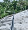
i found a pic of an original astroplane with expanded legs on an old memory stick,
my buddy Goldfinger sent me the picks years ago when we used to talk on paltalk,
i will post it when i get an image hosting site to work
 
Last edited:
  • Like
Reactions: tecnicoloco
Bob hold off, I'm not supposed to be laughing so hard...it puts pressure on my old heart. When I was younger...everything looked bigger, it could have been a 40' scaffold pole.
 
Last edited:
  • Like
Reactions: Slowmover
Works the opposite way round for me Eddie,

i have been stuck up that pole in the dark & rain with a sigma2 or electronica special & my dad made my brother come down & leave me to it, i was slipping & sliding but i got it up, i was fearless and determined back then,


last time i went up in the tree to get what was left of the poles i went up & onto the pole & got jelly leg, never had that before climbing anything,

my mate was laughing his ass off at me & said come down i will do it, he got up & also got jelly leg, he was stuck for a while clinging to the top of the ladder like a limpet,
at least i got off the ladder onto the pole,

it seems much higher now than it did when i was in my teens.

MK1 Astroplane radial joints
 
Last edited:
  • Like
Reactions: Slowmover
Ok, Bob I think I got the A/P model to working, and IMO with more predictable and better results. I had to add the mounting hub...like I used back in 2013 however.

Big thing is, I don't have to worry about just having to use a 1" mast...without seeing EZNEC showing a corruptible error message. So, these models both have 1.50" mast from hub mount to ground, excepting for the 2" Isolation at the bottom of the antenna mast, which is192" inches long and extending some distance below the radial loop.

I see very little bandwidth improvement comparing the full length whip with these models over Real Earth. The gain is improved a little with the longer radiator.

I did not mess with the model with the Top Hat, I used a spacing of 6" inches at the radials to mast bracket, and did nothing trying to fiddle with the resistance or the reactance.

The Top Hat model shows a very good improved match, if I change the frequency to 26.965 MHz. But, my A/P model still looks like it could have been cut for the old 23 channel radios. Just a guess though.


Attachments

  • AP wTop Hat vs. AP wFull 0.25w .pdf
    2.2 MB · Views: 14
Last edited:
Good job Eddie (y),

i don't understand what you did with the wires for the bracket but i see the junctions in the transmission-lines are now level as they should be & you got a good match,

do you think that was the problem with the other AP models & your new bracket fixed the alignment ?

i doubt you would notice much in the real world by using the full size upper 1/4wave but its showing a small improvement.
 
i don't understand what you did with the wires for the bracket but i see the junctions in the transmission-lines are now level as they should be & you got a good match,

With my first model of the A/P, I tried to make the model look as much like the real antenna as I could. That's because, I didn't know any better back then. So, that is what I just tried doing again Bob, the way I did the A/P in 2013. That was just to see if that old idea worked and if it made any difference vs. the way I've modeled the feed point location for several years now.

So, I hand wrote all the A/P dimensions that I used in this new 'Old' A/P model...even though dimensions are said to, "...really not matter when making comparisons," as some have claimed. :LOL::LOL::LOL:

Before I made the A/P model, I posted in #470 above, I talked about what I was planning to do...in giving one last additional effort to try and get my A/P model to work right, and before I made any further comparisons between the Top Hat version and the full 1/4 wave version.

So Bob, I can't explain what it is you don't understand...unless maybe you pick some particular issue and ask me about it. I'm open.

do you think that was the problem with the other AP models & your new bracket fixed the alignment ?

Well, you reminded me how important it is, in this case, to get the segment locations in the same plane...among closely spaced wires, parallel or not. I think you are right-on-point with this particular issue. So, in light of this..,what do you think?

i doubt you would notice much in the real world by using the full size upper 1/4wave but its showing a small improvement.

Here again, we see a small difference to be noted in some details for an antenna, or in a Patent, both like in this case. But, let some folks get this information...and then we're likely to hear another Fish Story about what the report means. CBBS

Bob again, I had a problem with my A/P models in the past, so I was just trying another idea that might work. As far as accurate dimensions go...maybe Alexis can get some good measurements and we will see if we can rule out dimensions as being the problem.

Now I'm back to the beginning of the post...so I'll stop.
 
Last edited:
No issue here Eddie,
I just don't understand the implications of what you did with the bracket and multiple wires, it seems to have worked,

I don't know what having junctions not level in transmission-lines does to a model,
I remembered reading that years ago during the sigma4 thread,

if you are trying to replicate the real antenna & get it to tune where the real antenna is tuned then you do need the right dimensions & the knowhow to input those dimensions correctly in NEC,

what use would EZNEC be if it was not like that,

my interested was in trying to prove the astroplane is a form of inverted sleeve monopole radiating through cmc like a 1/2wave open sleeve antenna with 1/4wave sleeve elements on a 1/4wave mast turned upside down, which is where I started at the beginning of this thread,

with your models & DB's models I am satisfied that Is what the astroplane is (y)

There's nothing special about its gain & avanti never claimed it had as much gain as their 5/8wave,

but under the regulations it was designed for it does have a small advantage over groundplane antennas which it was competing against because it puts current maxima higher above ground and there's no lossy burn me up matching involved.

Avanti advertising exaggerates the point & lie about where the center of radiation is on a groundplane unless its a 1/4wave groundplane.
 
I don't know what having junctions not level in transmission-lines does to a model,
I remembered reading that years ago during the sigma4 thread,

I can show you what happens with this model, and it is not much of a difference, even if I make the segments in the mast close to twice as big as the segments in the 2 radials. I'm not sure, but I would bet this rule in modeling is far more important in higher frequencies than at HF. Where have we heard this before?

if you are trying to replicate the real antenna & get it to tune where the real antenna is tuned then you do need the right dimensions & the knowhow to input those dimensions correctly in NEC,

I know you're right Bob. I have no allusions that I can make a model with such accuracy, but again I would bet I can get closer than I ever imagined possible.

Without Real World testing and maybe proving a model, or having Real World experience that might suggest a model is close, most modeling I see and do...just gives us an idea of what might be possible, and sometimes it doesn't.
 
  • Like
Reactions: bob85
Here are some measurements of my NOS Astro- Plane antenna. See pics.
 

Attachments

  • 30510039-2C9A-4944-808D-9372C3C63316.jpeg
    30510039-2C9A-4944-808D-9372C3C63316.jpeg
    203.6 KB · Views: 10
  • C4C44A2B-6BD3-497F-A932-6C528EC5A6DC.jpeg
    C4C44A2B-6BD3-497F-A932-6C528EC5A6DC.jpeg
    364.9 KB · Views: 10
  • 130B238F-CAC2-49A4-92EA-4B98CA09E41C.jpeg
    130B238F-CAC2-49A4-92EA-4B98CA09E41C.jpeg
    470.4 KB · Views: 9
  • AFFD0A2F-7BE6-46EF-B909-F405F683E1A6.jpeg
    AFFD0A2F-7BE6-46EF-B909-F405F683E1A6.jpeg
    207 KB · Views: 9
More pics
 

Attachments

  • 69295843-9C1D-44B5-8F9F-4B693407E7A6.jpeg
    69295843-9C1D-44B5-8F9F-4B693407E7A6.jpeg
    2.2 MB · Views: 8
  • 26859A9E-D92F-41F1-AC58-E4CFC8FD88A7.jpeg
    26859A9E-D92F-41F1-AC58-E4CFC8FD88A7.jpeg
    1.5 MB · Views: 9
  • 8FE9F649-9924-4C50-895B-C89C6CA2A49F.jpeg
    8FE9F649-9924-4C50-895B-C89C6CA2A49F.jpeg
    4.2 MB · Views: 8
  • 301C95C4-AB54-4446-87BF-18748E55373D.jpeg
    301C95C4-AB54-4446-87BF-18748E55373D.jpeg
    2 MB · Views: 8
  • B376F276-7F39-4CD5-A79A-3A22DECE00F3.jpeg
    B376F276-7F39-4CD5-A79A-3A22DECE00F3.jpeg
    1.1 MB · Views: 8
  • A90A552B-9365-40D2-8EC7-3F38EBA81A03.jpeg
    A90A552B-9365-40D2-8EC7-3F38EBA81A03.jpeg
    987.7 KB · Views: 6
More
 

Attachments

  • 64F74F3A-CF01-4C31-9B8D-94E358B3829C.jpeg
    64F74F3A-CF01-4C31-9B8D-94E358B3829C.jpeg
    273.5 KB · Views: 6
  • 4BA05C51-3E20-46FA-8E87-5CA3DD9A22EC.jpeg
    4BA05C51-3E20-46FA-8E87-5CA3DD9A22EC.jpeg
    375.8 KB · Views: 7
  • AE5AEFE5-C3F2-40C7-AC5C-FE6B5071EA52.jpeg
    AE5AEFE5-C3F2-40C7-AC5C-FE6B5071EA52.jpeg
    257.6 KB · Views: 6
  • AE99B8CE-AF08-46FB-BC3F-58694AD2F7A5.jpeg
    AE99B8CE-AF08-46FB-BC3F-58694AD2F7A5.jpeg
    526.8 KB · Views: 7
  • 5143241C-0255-4765-A1B5-012EBB598487.jpeg
    5143241C-0255-4765-A1B5-012EBB598487.jpeg
    344.9 KB · Views: 7
  • C525C9FE-2AD0-41AC-A130-06F624C6F727.jpeg
    C525C9FE-2AD0-41AC-A130-06F624C6F727.jpeg
    365.1 KB · Views: 6
  • 24A6B81C-9C81-4E85-9168-32DF763C911F.jpeg
    24A6B81C-9C81-4E85-9168-32DF763C911F.jpeg
    276.5 KB · Views: 6
  • B8E91AF2-02CE-446E-8DCB-4EE037DFE032.jpeg
    B8E91AF2-02CE-446E-8DCB-4EE037DFE032.jpeg
    303.7 KB · Views: 6
  • BB561FDA-21D9-4846-B12B-3EBCDE175D58.jpeg
    BB561FDA-21D9-4846-B12B-3EBCDE175D58.jpeg
    233 KB · Views: 6
  • 6CF06F84-9926-4F83-95EE-5E9B1629D7E8.jpeg
    6CF06F84-9926-4F83-95EE-5E9B1629D7E8.jpeg
    530 KB · Views: 7
Last ones
 

Attachments

  • CBC13364-347F-468F-9FF7-1231C3F8C4CD.jpeg
    CBC13364-347F-468F-9FF7-1231C3F8C4CD.jpeg
    530 KB · Views: 7
  • 43647119-C5EE-4F08-AECF-C15899A5650A.jpeg
    43647119-C5EE-4F08-AECF-C15899A5650A.jpeg
    769.8 KB · Views: 8
  • CBC60BD0-B574-41E5-BC1A-266853EAE08C.jpeg
    CBC60BD0-B574-41E5-BC1A-266853EAE08C.jpeg
    518.3 KB · Views: 7
  • CF55D549-1EB9-411F-94BD-2391751AD712.jpeg
    CF55D549-1EB9-411F-94BD-2391751AD712.jpeg
    863.4 KB · Views: 7
Thank you Alexissss. I will try your dimensions and see what happens.

As usual, you did an excellent job with plenty of great images.(y)(y)(y)

Bob, I don't think the problem with these A/P models was just a dimensions here and there. I still think it was the location of the feed point I've been using. That said, this will take some more work to be sure.
 
Last edited:
I don't know what having junctions not level in transmission-lines does to a model,
I remembered reading that years ago during the sigma4 thread,

Bob, here is an A/P model dated 092820, that I was fiddling with after I read the post from Alexis with his dimensions.

Like I promised, I made a few changes and then decided to mess-up the segments on the mast, so they were about twice the length of those on the radials...Compare the little green dot segment connection points now, and then check the AG report, the Free Space pattern, and the match. Also the model still has a 1.50" inch mast, and no critical error message.

Not much has changed, the A/P is still a CFHW vertical antenna.

I also set the frequency to 26.965 MHz where it is resonant. The model has not changed much, even with such and error that we've heard about that was proclaimed on-high to be a critical error in modeling in the HF band.
 

Attachments

  • Eznec Segmentation Rules.pdf
    646 KB · Views: 8
Last edited:
  • Like
Reactions: Alexis Mercado

dxChat
Help Users
  • No one is chatting at the moment.