
You are using an out of date browser. It may not display this or other websites correctly.
You should upgrade or use an alternative browser.
You should upgrade or use an alternative browser.
-
You can now help support WorldwideDX when you shop on Amazon at no additional cost to you! Simply follow this Shop on Amazon link first and a portion of any purchase is sent to WorldwideDX to help with site costs.
-
A Winner has been chosen for the 2026 July 4th Retevis RA89R Giveaway! Click Here to see who won!
Channel 9 mod question for a newbie
- Thread starter Klint
- Start date
Klint:
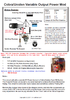
Are you aware that you are telling us, you have a Cobra 29 LTD, but your board jumper scheme is for a Cobra 25 LTD...
How?
Cobra 29's use a "twin coil" can shield case - you use L21 and L27 - in a Cobra 29 it's just L21. (just north of your Final and Driver heat sink and mounting panel in your photo) - JV6 is the ID for Cobra 25 not JP36 for Cobra 29 - and Cobra 29's use a LONGER jumper.
Yeah, definitely tells us your radio has a different point of origin...
Here's an example of what I usually get - so your newer board HOPEFULLY is not that much different...
Now that I know, your mod insertion point is JV6 with your Resistor Cap mod. Just be careful - yes, you do have a different board in there and you cut off your board ID...so we can only presume you want to go thru with this I will warn you the JV6 holes, the one towards the Rear panel - needs to have your caps NEGATIVE (Cathode) or Banded side - that lead goes towards it.

The Resistor can be any value between 25 to as much as 100 ohms, this resistor affects the DC power level and drops it down to force the Final to have less input power to amplify so it lowers the carrier power produced at the antenna jack - but too much or too high of ohmic value, you can destroy the Driver from lack of power (you starve it - this can cause damage), you don't want that.
Cap values? Just make sure you're using 25V or so in WVDC (Watts/Volts in DC current) and the use of polarized works ok - values between 33uF on up to 680uF produce the best volume to swing with lower values providing the lower swing rates and less distortion. IF you go too high, you can damage the Driver from swamping the power it needs to work with audio signal - which is an AC type signal - and if you don't have enough DC voltage in there going thru the Driver - you can destroy it not just from "starvation" but by excessive non-DC (READ: True AC current) that it can't use or develop power from.
Again, you want to do this, proceed with care - don't overdo the mod - you're safer with more conservative values - this isn't written in stone so you can swap values and listen - hear - monitor - the results as you go.
I know this will be a learning curve for you - don't make it too steep or harder than it has to be.
Are you aware that you are telling us, you have a Cobra 29 LTD, but your board jumper scheme is for a Cobra 25 LTD...
How?
Cobra 29's use a "twin coil" can shield case - you use L21 and L27 - in a Cobra 29 it's just L21. (just north of your Final and Driver heat sink and mounting panel in your photo) - JV6 is the ID for Cobra 25 not JP36 for Cobra 29 - and Cobra 29's use a LONGER jumper.
Yeah, definitely tells us your radio has a different point of origin...
Here's an example of what I usually get - so your newer board HOPEFULLY is not that much different...
Now that I know, your mod insertion point is JV6 with your Resistor Cap mod. Just be careful - yes, you do have a different board in there and you cut off your board ID...so we can only presume you want to go thru with this I will warn you the JV6 holes, the one towards the Rear panel - needs to have your caps NEGATIVE (Cathode) or Banded side - that lead goes towards it.
The Resistor can be any value between 25 to as much as 100 ohms, this resistor affects the DC power level and drops it down to force the Final to have less input power to amplify so it lowers the carrier power produced at the antenna jack - but too much or too high of ohmic value, you can destroy the Driver from lack of power (you starve it - this can cause damage), you don't want that.
Cap values? Just make sure you're using 25V or so in WVDC (Watts/Volts in DC current) and the use of polarized works ok - values between 33uF on up to 680uF produce the best volume to swing with lower values providing the lower swing rates and less distortion. IF you go too high, you can damage the Driver from swamping the power it needs to work with audio signal - which is an AC type signal - and if you don't have enough DC voltage in there going thru the Driver - you can destroy it not just from "starvation" but by excessive non-DC (READ: True AC current) that it can't use or develop power from.
Again, you want to do this, proceed with care - don't overdo the mod - you're safer with more conservative values - this isn't written in stone so you can swap values and listen - hear - monitor - the results as you go.
I know this will be a learning curve for you - don't make it too steep or harder than it has to be.
Attachments
Hope this doesn't become our standard reply to new members.
I was however able to pull enough individual letters from it to spell Welcome.")
")


i must agree with you 100% and WELCOME KLINT
Klint:
Are you aware that you are telling us, you have a Cobra 29 LTD, but your board jumper scheme is for a Cobra 25 LTD...
How?
Cobra 29's use a "twin coil" can shield case - you use L21 and L27 - in a Cobra 29 it's just L21. (just north of your Final and Driver heat sink and mounting panel in your photo) - JV6 is the ID for Cobra 25 not JP36 for Cobra 29 - and Cobra 29's use a LONGER jumper.
Yeah, definitely tells us your radio has a different point of origin...
Here's an example of what I usually get - so your newer board HOPEFULLY is not that much different...View attachment 28419
Now that I know, your mod insertion point is JV6 with your Resistor Cap mod. Just be careful - yes, you do have a different board in there and you cut off your board ID...so we can only presume you want to go thru with this I will warn you the JV6 holes, the one towards the Rear panel - needs to have your caps NEGATIVE (Cathode) or Banded side - that lead goes towards it.
View attachment 28420
The Resistor can be any value between 25 to as much as 100 ohms, this resistor affects the DC power level and drops it down to force the Final to have less input power to amplify so it lowers the carrier power produced at the antenna jack - but too much or too high of ohmic value, you can destroy the Driver from lack of power (you starve it - this can cause damage), you don't want that.
Cap values? Just make sure you're using 25V or so in WVDC (Watts/Volts in DC current) and the use of polarized works ok - values between 33uF on up to 680uF produce the best volume to swing with lower values providing the lower swing rates and less distortion. IF you go too high, you can damage the Driver from swamping the power it needs to work with audio signal - which is an AC type signal - and if you don't have enough DC voltage in there going thru the Driver - you can destroy it not just from "starvation" but by excessive non-DC (READ: True AC current) that it can't use or develop power from.
Again, you want to do this, proceed with care - don't overdo the mod - you're safer with more conservative values - this isn't written in stone so you can swap values and listen - hear - monitor - the results as you go.
I know this will be a learning curve for you - don't make it too steep or harder than it has to be.
Yes definately a learning curve , but very interesting stuff ...Thanks for the info . The scary thing is doing the soldering with all the close tolerances on the solder side of the board. Not much room for error. .HahaKlint:
Are you aware that you are telling us, you have a Cobra 29 LTD, but your board jumper scheme is for a Cobra 25 LTD...
How?
Cobra 29's use a "twin coil" can shield case - you use L21 and L27 - in a Cobra 29 it's just L21. (just north of your Final and Driver heat sink and mounting panel in your photo) - JV6 is the ID for Cobra 25 not JP36 for Cobra 29 - and Cobra 29's use a LONGER jumper.
Yeah, definitely tells us your radio has a different point of origin...
Here's an example of what I usually get - so your newer board HOPEFULLY is not that much different...View attachment 28419
Now that I know, your mod insertion point is JV6 with your Resistor Cap mod. Just be careful - yes, you do have a different board in there and you cut off your board ID...so we can only presume you want to go thru with this I will warn you the JV6 holes, the one towards the Rear panel - needs to have your caps NEGATIVE (Cathode) or Banded side - that lead goes towards it.
View attachment 28420
The Resistor can be any value between 25 to as much as 100 ohms, this resistor affects the DC power level and drops it down to force the Final to have less input power to amplify so it lowers the carrier power produced at the antenna jack - but too much or too high of ohmic value, you can destroy the Driver from lack of power (you starve it - this can cause damage), you don't want that.
Cap values? Just make sure you're using 25V or so in WVDC (Watts/Volts in DC current) and the use of polarized works ok - values between 33uF on up to 680uF produce the best volume to swing with lower values providing the lower swing rates and less distortion. IF you go too high, you can damage the Driver from swamping the power it needs to work with audio signal - which is an AC type signal - and if you don't have enough DC voltage in there going thru the Driver - you can destroy it not just from "starvation" but by excessive non-DC (READ: True AC current) that it can't use or develop power from.
Again, you want to do this, proceed with care - don't overdo the mod - you're safer with more conservative values - this isn't written in stone so you can swap values and listen - hear - monitor - the results as you go.
I know this will be a learning curve for you - don't make it too steep or harder than it has to be.