B
BOOTY MONSTER
Guest
i was surfing around and found a interesting thread over at QRZ about coax chokes and common mode currents . W8JI had a few gems he shared and a nice link to a graph about coax chokes . i thought i post links to both the thread here and the graph/info .
http://forums.qrz.com/showthread.php?t=248458
heres a few of his nuggets that i found interesting ...
++++++++++++++++++++++++++++++++
"The conditions that must exist for no feedline radiation or common mode are:
...............................................
With an unbalanced line the shield has to have zero voltage to other areas of the shield outside the shield everywhere along the shield, and has to have exactly equal and opposite currents flowing into and out of the center and shield at each end.
..............................................
even 4 quarter wave radials on a groundplane is the voltage from the common point to other areas downstream on the coax is not zero, so a current flows on the outside of the shield.
.............................................
I learned how bad that effect was designing a commercial groundplane antenna for use near six meters, and when measuring elevated radials. With only four radials a substantial current could flow over the feedline shield.
Common mode is not caused by high SWR. It is caused by less than perfect ground."
++++++++++++++++++++++++++++++
so even though more than 4 four elevated ground elements may have no noticeable effect on our tx and rx having a bunch more could/would eliminate CMC,s ,,,,,, if im understanding this correctly . so it seems that since thats not practical for a elevated antenna then a choke is necessary , not just a option .
he also provided a link to info on air and ferrite core chokes . thank you G3TXQ")
Common-mode chokes
G3TXQ says that air core chokes are only reactive (which i honestly dont truly understand what that means) . but i was surprised when he said ......
"Reactive chokes have the disadvantage that they can "resonate" with a CM impedance path that is also reactive but of opposite sign - in some cases actually increasing the CM current flow rather than choking it;"
when i was talking with eddie/marconi over the weekend we discussed my coax choke plan of using 10 or 12 wraps and he said he thought 4 or 5 might be better for me . this graph supports that and if im reading/understanding it correctly using 10-15 wraps on the 4 inch former i have would have actually increased any CMC issues that i may have . i found this pretty interesting as i didnt think you could have to much choke coil , but there is a optimal amount for a given bandwidth/ frequency span . there also seems to be a optimal size as well considering the 7 inch air chokes really increase the CMC's on 11 meters since its off the scale with a narrower bandwidth of use than the smaller choke .
if someone can confirm im understanding correctly id appreciate it")
heres G3TXQ article and graph .
++++++++++++++++++++++++++++++++++++=
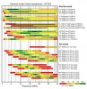
"The following chart presents the results of impedance measurements made on a variety of common-mode choke implementations across the frequency range 1MHz to 30MHz. Amateur frequency allocations are indicated approximately by the vertical grey bands.
The colours of the bars indicate the magnitude of the CM (common-mode) impedance; however, depending on the style of choke and the type of ferrite material used for the core, that impedance might be mostly Resistive, mostly Reactive, or somewhere in between. The black bars at the bottom of the coloured bars indicate the range of frequencies over which the choke impedance is predominantly Resistive - that is Rs>Xs. No black bars are shown for the air-cored chokes because their impedance is almost entirely Reactive apart from a very small band of frequencies around resonance.
Reactive chokes have the disadvantage that they can "resonate" with a CM impedance path that is also reactive but of opposite sign - in some cases actually increasing the CM current flow rather than choking it; Resistive chokes have the disadvantage that if they have insufficient impedance to reduce the CM current to a very low value, there may be significant core heating.
Aim to choose a choke which has a high impedance and is Resistive over the frequency range of interest.
I hope to add more data as I make further measurements."
http://forums.qrz.com/showthread.php?t=248458
heres a few of his nuggets that i found interesting ...
++++++++++++++++++++++++++++++++
"The conditions that must exist for no feedline radiation or common mode are:
...............................................
With an unbalanced line the shield has to have zero voltage to other areas of the shield outside the shield everywhere along the shield, and has to have exactly equal and opposite currents flowing into and out of the center and shield at each end.
..............................................
even 4 quarter wave radials on a groundplane is the voltage from the common point to other areas downstream on the coax is not zero, so a current flows on the outside of the shield.
.............................................
I learned how bad that effect was designing a commercial groundplane antenna for use near six meters, and when measuring elevated radials. With only four radials a substantial current could flow over the feedline shield.
Common mode is not caused by high SWR. It is caused by less than perfect ground."
++++++++++++++++++++++++++++++
so even though more than 4 four elevated ground elements may have no noticeable effect on our tx and rx having a bunch more could/would eliminate CMC,s ,,,,,, if im understanding this correctly . so it seems that since thats not practical for a elevated antenna then a choke is necessary , not just a option .
he also provided a link to info on air and ferrite core chokes . thank you G3TXQ
Common-mode chokes
G3TXQ says that air core chokes are only reactive (which i honestly dont truly understand what that means) . but i was surprised when he said ......
"Reactive chokes have the disadvantage that they can "resonate" with a CM impedance path that is also reactive but of opposite sign - in some cases actually increasing the CM current flow rather than choking it;"
when i was talking with eddie/marconi over the weekend we discussed my coax choke plan of using 10 or 12 wraps and he said he thought 4 or 5 might be better for me . this graph supports that and if im reading/understanding it correctly using 10-15 wraps on the 4 inch former i have would have actually increased any CMC issues that i may have . i found this pretty interesting as i didnt think you could have to much choke coil , but there is a optimal amount for a given bandwidth/ frequency span . there also seems to be a optimal size as well considering the 7 inch air chokes really increase the CMC's on 11 meters since its off the scale with a narrower bandwidth of use than the smaller choke .
if someone can confirm im understanding correctly id appreciate it
heres G3TXQ article and graph .
++++++++++++++++++++++++++++++++++++=
"The following chart presents the results of impedance measurements made on a variety of common-mode choke implementations across the frequency range 1MHz to 30MHz. Amateur frequency allocations are indicated approximately by the vertical grey bands.
The colours of the bars indicate the magnitude of the CM (common-mode) impedance; however, depending on the style of choke and the type of ferrite material used for the core, that impedance might be mostly Resistive, mostly Reactive, or somewhere in between. The black bars at the bottom of the coloured bars indicate the range of frequencies over which the choke impedance is predominantly Resistive - that is Rs>Xs. No black bars are shown for the air-cored chokes because their impedance is almost entirely Reactive apart from a very small band of frequencies around resonance.
Reactive chokes have the disadvantage that they can "resonate" with a CM impedance path that is also reactive but of opposite sign - in some cases actually increasing the CM current flow rather than choking it; Resistive chokes have the disadvantage that if they have insufficient impedance to reduce the CM current to a very low value, there may be significant core heating.
Aim to choose a choke which has a high impedance and is Resistive over the frequency range of interest.
I hope to add more data as I make further measurements."