Let me check, but the board says pb010 and there is no reference to dx on the face. I think this may be a Frankenstein radio. Figures.

You are using an out of date browser. It may not display this or other websites correctly.
You should upgrade or use an alternative browser.
You should upgrade or use an alternative browser.
-
You can now help support WorldwideDX when you shop on Amazon at no additional cost to you! Simply follow this Shop on Amazon link first and a portion of any purchase is sent to WorldwideDX to help with site costs.
-
A Winner has been chosen for the 2026 July 4th Retevis RA89R Giveaway! Click Here to see who won!
Cobra 148 GTL variable deadkey mod
- Thread starter Dark Star
- Start date
If the board says PB-010, you're good to go. The modulator upgrade is the circuit used on dual final exports. The 148GTL-DX has provision for dual finals, and the component markings are already on the board. I'll post that mod if you're interested.
- 399
- 399
Last edited:

Okay, it has the different transistors in those spots, but tr52 I can't make it out, and i havent located r295 yet. The face just says 148gtl and the rear plate is gone. I think it's a dx model, but the faceplate is wrong. It has to be, after doing some looking around the Internet. Not important really. After realizing that there are different versions of this radio, I am clearly not on the same page with the swing mod the op was referring to. I will get back on the porch.CG -
I'm confused. What radio do you have: A standard 148GTL, or a 148GTL-DX (PB-010 board) ?? If its the 010 board, and it has a 2SB817 in the TR51 position, you need to check that TR53 is a 2SA1012 (or equiv), and TR52 is a 2SD471 (or equiv). Then check that R295 is a 47 ohm/1 watt resistor. This is the complete PB-010 modulator upgrade, and doubles the modulator output. If the transistors and the resistor haven't been changed the 2SB817 upgrade is useless. BTW, R295 should be mounted above the board for cooling, and small clip-on heat sinks should be installed on TR52 and 53. Good Luck. 73.
- 399
If the board says PB-010, you're good to go. The modular upgrade is the circuit used on dual final exports. The 148GTL-DX has provision for dual finals, and the component markings are already on the board. I'll post that mod if you're interested.
- 399
Thanks, I have that dual final upgrade printed out somewhere, I might try it. I guess whoever upgraded the modulator didn't get that far, as it only has 1 final in it. Yes, there are silkscreen designators for the supporting parts of the second final. I can start a new thread instead of hijacking this one to Hades. (Too late)
Nomad, I used your version of the variable carrier control on a 148 over the weekend.We use the SWR Cal control. Unhook all 3 wires that lead to the control so you can splice a longer wire and sleeve the lap splices to each.
You first cut the trace between the wiper of the original carrier-level trimpot and the circuitry to the rear of it. A wire now goes from the now-separated wiper of the trimpot to the clockwise lug of the front-panel control.
A 10k 1/4W resistor now goes to the foil trace to the rear of where it was severed from the trimpot's center (wiper) lug. The other end of this resistor goes to the handy ground foil adjacent. Leave a quarter inch or so of resistor lead sticking up from the trace that was severed from the trimpot. A wire from the center (wiper) lug of the SWR Cal control goes to the rear of the radio next to the original carrier trimpot. Lap-splice the anode (no band) end of a generic 1N4148 type diode to the end of this wire. The cathode (band) end of this diode goes to the trace we severed from the carrier trimpot's center lug. If you left a small piece of the 10k resistor's lead sticking out, lap-solder the band end of this diode to it.
The counterclockwise lug of the SWR Cal control gets a wire leading back to the original carrier trimpot. Where you connect this wire will determine what the minimum carrier level will be at the left-most travel of the SWR Cal knob. Simply grounding this wire is the easy answer. A 1k trimpot between the wire and ground will let you adjust the minimum carrier setting. The original carrier trimpot now sets the max carrier level.
It's popular to "power boost" the final stage. The bias-test wire that leads to the final transistor first gets used to set the final transistor's idle current on sideband/no audio to 60 mA. This wire gets the end cut off, stripped and soldered to the main power supply voltage, usually the center pin of the AM modulator transistor. This permits the PEP in AM mode to equal that seen in sideband.
Gotta shoot pics of this setup someday. Been doing it so long we never needed a record of it to train a new tech.
One thing we learned to check first is R228, a 560-ohm 1/4W resistor just to the rear of the carrier trimpot. It gets clipped as a "swing" mod. Makes an average-reading wattmeter happier, but reduces the audio at the other end. Putting it back always improves the audio. And if R228 looks undisturbed, you're good to go.
73
It works awesome. So much better than just removing VR10 and and wiring to a pot.
Being able to limit the max carrier is a must on these radios in my opinion.
Just wanted to say thanks for sharing.
Anyone considering adding a variable to a 148, this is the best method for sure!
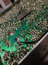
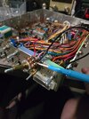
Had to get some help but, thank you for the help Nomad! im going to post some pics if anyone wants to use them have at it. If yall see anything i could have done better hit me with it just here to learn.
Attachments


dxChat
- No one is chatting at the moment.