• You can now help support WorldwideDX when you shop on Amazon at no additional cost to you! Simply follow this Shop on Amazon link first and a portion of any purchase is sent to WorldwideDX to help with site costs.

Cobra 2000 GTL questions/ help needed

This is where a 'scope pays for itself to anyone who does this a lot.

Finding a DC-voltage fault is great, since this will usually cause loss of signal, whether in the receiver or transmitter.

But if the fault is in a part that doesn't disrupt any normal DC voltages, it becomes necessary to follow the signal that's being lost. In this case the transmit signal.

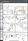
Any time there is no transmit signal, even a weak one you can 'sniff' with a spare radio, peoples' eyes will focus on IC5, the "S042P" transmit mixer chip. This is where the 7.8 MHz carrier (or sideband) gets mixed with the 35 MHz PLL's vco. The 27 MHz signal originates in this part.

And they almost never fail. Really sounds as if one of the two inputs to this chip has gone missing.

But which one? This is much more common in my experience. IC5 failure is a once-every-few-hundred radios kind of fault, if even that often.

DC-voltage measurements will lead you to an "easy" fault. But this one is sounding less easy every time a new DC voltage gets checked, and reads like it should.


This will be true when the driver and final have a drive signal, and pull normal current from the AM modulator circuit. But when there is no carrier drive, the final and driver don't draw very much collector current. R193 will drive up the voltage reading on those two test points when AM carrier drive is lost. The reading he saw makes sense, considering R193.

73
OK I picked up a scope and started looking at SO42P, I was seeing 35.8MHz on pins 11&13 0volts in both RX and TX and nothing on Pins 7&8 but did see .54vdc on both RX & TX. I did trace the voltage issue back to IC4 MB3756 luckily had a spare chassis from from long, long time ago so I pulled from the old and installed.
Now on SO42P I’m getting the following:
PIN 13 & 11
0.0 Vdc RX
1.3 Vdc TX
35.825 MHz

PIN 7 & 8
.54 Vdc RX
2.9 Vdc TX
no frequencies seen

PIN 2, 3 & 5
.54 Vdc RX
8.0 Vdc TX

Also I see the Modulation meter swing in AM but not in USB or LSB with no watts out. I can now hear modulation clear using a second radio in all Modes.
 
Should have 7.8 MHz carrier. Won't transmit without it.

Time to 'scope each side of D53, feeds the 7.8 carrier into L48, which feeds into pins 7&8. If you have it there, L48 looks suspect. If you don't, time to follow upstream from there to see where it stops.

73
I had a little time today so I probed both sides of D53 and dint get anything. I attached a pic of the schematic I followed to FT3. I’m not sure why but I see the 7.8MHz at both TP62 & 63 but not TP61 or 64. The components marked in green are ones I checked to make sure not open or shorted all test good and in spec. Not sure if I’m following the correct path but FT3 is the only reference I seen for 7.8MHz.
 

Attachments

  • IMG_2320.png
    IMG_2320.png
    2.1 MB · Views: 3
just so we are all on the same page, can you tell us exactly what does and doesn't work right now?

it sounds to me like you can hear yourself on another radio in all modes but aren't showing any watts out.
is that correct?
if so, how are you measuring your output?
LC
 
just so we are all on the same page, can you tell us exactly what does and doesn't work right now?

it sounds to me like you can hear yourself on another radio in all modes but aren't showing any watts out.
is that correct?
if so, how are you measuring your output?
LC
Correct if I take a handheld cb and put the rubber antenna inside the circuit board area I can hear myself on all channels AM, SSB & USB. receive is good on all channels, AM & SSB. All my voltages at IC5 mixer are correct and I see 34 MHz at pins 11 & 13 but I don’t see the 7.8 MHz at pins 7&8. I traced the circuit back and see the 7.8 MHz at FT3 from C51 side. When I probe the other side of FT3 at the C52 side it’s weak. I decided To lift R60 and then I see the 7.8MHz no issues to pins 7&8 at IC5. I checked R30 and it’s good and voltage is correct in AM TX and SSB. I put R60 back in and it all falls back to nothing?
I then ran short on patients for the day and time.
To measuring output I am using a Bird 1 watt slug and I also have a tap going to an Oscilloscope.
 
im a little confused by your last post.

What im talking about it putting your scope probe on pins 7 or 8 in TX mode and turning the slug in L48 looking for a peak in amplitude.
LC
 
  • Like
Reactions: NZ8N
No I’m only seeing 2.5KHz max on one side and 3.3MHz max on other
In a circuit that combines 35 MHz with 7.8 MHz, to obtain 27 MHz neither of those numbers appears meaningful.

Are you using a digital 'scope that tries to count the displayed waveform's frequency?

If so, those numbers are most likely bogus. A digital 'scope requires a minimum input level to display the correct frequency. And the waveform must have only one frequency in it.

But a mixer circuit's function is to combine two frequencies.

What we're interested in is what comes out of IC5. If the inputs at pins 11+13, and the other input at pins 7+8 both appear healthy, the output at pins 2+3 should have a larger amplitude.

Since you can hear a signal in the handheld radio, you know the mixer chip is doing its job, combining 7.8 and 35 MHz. The signal is getting lost somewhere downstream from IC5.

A radio with an S-meter allows you to see if the tuning slugs on L45, 46, 47 and 48 each respond with a proper peak when adjusted. If they do, that circuit is probably okay. And if you can't get a proper peak from that slug, it indicates trouble in that circuit.

The tip of a 'scope probe tends to disrupt the peak adjustment of those coils when it touches the circuit. Best way to check those four in a 'dead' transmitter is with a receiver. It won't disrupt the peak adjustment of a coil slug the way a probe tip tends to do.

The behavior of those four slugs can be a major diagnostic clue, but not when a 'scope probe's tip is touching one of them.

73
 
  • Like
Reactions: loosecannon
In a circuit that combines 35 MHz with 7.8 MHz, to obtain 27 MHz neither of those numbers appears meaningful.

Are you using a digital 'scope that tries to count the displayed waveform's frequency?

If so, those numbers are most likely bogus. A digital 'scope requires a minimum input level to display the correct frequency. And the waveform must have only one frequency in it.

But a mixer circuit's function is to combine two frequencies.

What we're interested in is what comes out of IC5. If the inputs at pins 11+13, and the other input at pins 7+8 both appear healthy, the output at pins 2+3 should have a larger amplitude.

Since you can hear a signal in the handheld radio, you know the mixer chip is doing its job, combining 7.8 and 35 MHz. The signal is getting lost somewhere downstream from IC5.

A radio with an S-meter allows you to see if the tuning slugs on L45, 46, 47 and 48 each respond with a proper peak when adjusted. If they do, that circuit is probably okay. And if you can't get a proper peak from that slug, it indicates trouble in that circuit.

The tip of a 'scope probe tends to disrupt the peak adjustment of those coils when it touches the circuit. Best way to check those four in a 'dead' transmitter is with a receiver. It won't disrupt the peak adjustment of a coil slug the way a probe tip tends to do.

The behavior of those four slugs can be a major diagnostic clue, but not when a 'scope probe's tip is touching one of them.

73
Yes I am using a digital scope to acquire frequency and what you say now makes perfect sense the scope want one frequency. I will pull out a radio with a meter and give that a go.
 
Check, replace C95.
Cobra 2ks and 148s will produce no transmit in any mode whatsoever, not even a wimper of output if that cap is bad. Seen it plenty of times. Replace it with another of the same value in UF but increase voltage rating to 25v.

Hope that helps.
 
  • Like
Reactions: NZ8N
When C95 goes bad, it fails as a short. Shuts down the supply voltage to IC3. All transmit signals come from IC3. As a rule, the 100 ohm resistor feeding into C95, R108 will appear overheated. We always replace R108 any time C95 goes bad. If the calibrated eyeball reveals visible damage to R108, C95 is bad.

Might or might not explain your fault, but we see it over and over.

73
 
  • Like
Reactions: NZ8N and Hawkeye351

dxChat
Help Users
  • No one is chatting at the moment.
  • @ Wildcat27:
    Hello I have a old school 2950 receives great on all modes and transmits great on AM but no transmit on SSB. Does anyone have any idea?
  • @ ButtFuzz:
    Good evening from Sunny Salem! What’s shaking?