
You are using an out of date browser. It may not display this or other websites correctly.
You should upgrade or use an alternative browser.
You should upgrade or use an alternative browser.
-
You can now help support WorldwideDX when you shop on Amazon at no additional cost to you! Simply follow this Shop on Amazon link first and a portion of any purchase is sent to WorldwideDX to help with site costs.
-
A Winner has been chosen for the 2026 July 4th Retevis RA89R Giveaway! Click Here to see who won!
Cobra 21 Ltd Classic MOSFET ?
- Thread starter D.R. Howell
- Start date
Thanks Low_Boy. Hopefully someone that has will be willing share a little insight on the mod!I believe loosecannon did one.
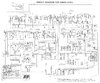
I worked on the Graphics in that thread - back in the days of CB Tricks, don't know if they can apply but the principles are there.

Remember that the MOSFET you use may need to have it's EN396 equivalent MODIFIED (in graphic it is a Diode in series with 470 ohm, and swamped with 3.3K) to work correctly on your application.
Other mods include a tweak to the limiter and audio EQ around the Audio Amp chip.
You can contact @loosecannon for further details...


Andy,I worked on the Graphics in that thread - back in the days of CB Tricks, don't know if they can apply but the principles are there.
View attachment 28066
Remember that the MOSFET you use may need to have it's EN396 equivalent MODIFIED (in graphic it is a Diode in series with 470 ohm, and swamped with 3.3K) to work correctly on your application.
Other mods include a tweak to the limiter and audio EQ around the Audio Amp chip.
You can contact @loosecannon for further details...
I'm trying to go through your audio mod and looking at the full schematic for both the 19LTD and 21LTD, I cant seem to place your mods.

You can't apply them directly - they are different boards, you can extrapolate...
And you're telling me you can or cannot extrapolate?
Ok, I've got some stuff on the schedule here to complete today - but if it goes well I can be back here to finish this and show you the SAME yet DIFFERENT (Bifurcation) of the two different Limiter designs and operation - they are essentially the same - just layout is different and the values are changed...
Limiter is still a PNP design and uses a Divider of R47 2.7K and R48 1K - change R47 SWAP IT with R39 15K - the positive rail side of the Divider - put R39 value in R47's place - change C42, the "sense cap" to a 1uF or even a 0.47uF - follow polarity. A non polarized can work here but no less than 224 or 0.22uF.
Remove C30.
I've got a better idea that keeps more parts in place and fewer problems...
C30 - REMOVE and REPLACE with what you took OUT at C42 (The 3.3uF) - again follow polarity.
See Below...I reworked your chip to show where I would work...

That takes care of the Limiter.
Ok?
The 21 you have is the KIA 7217 chip - a bit different but not meaning that it's not workable - just a different EQ and Pin out design... where did you get the schematic?
I don't know why you highlited those values unless it's from a clip from somewhere else - those are mic audio path mods
What LC worked on is the "Response" the limiter had - so re-read and look over the graphic I sent earlier - those mods are mostly for Limiter response and peaking.
And you're telling me you can or cannot extrapolate?
Ok, I've got some stuff on the schedule here to complete today - but if it goes well I can be back here to finish this and show you the SAME yet DIFFERENT (Bifurcation) of the two different Limiter designs and operation - they are essentially the same - just layout is different and the values are changed...
Limiter is still a PNP design and uses a Divider of R47 2.7K and R48 1K - change R47 SWAP IT with R39 15K - the positive rail side of the Divider - put R39 value in R47's place - change C42, the "sense cap" to a 1uF or even a 0.47uF - follow polarity. A non polarized can work here but no less than 224 or 0.22uF.
I've got a better idea that keeps more parts in place and fewer problems...
C30 - REMOVE and REPLACE with what you took OUT at C42 (The 3.3uF) - again follow polarity.
See Below...I reworked your chip to show where I would work...
That takes care of the Limiter.
Ok?
The 21 you have is the KIA 7217 chip - a bit different but not meaning that it's not workable - just a different EQ and Pin out design... where did you get the schematic?
I don't know why you highlited those values unless it's from a clip from somewhere else - those are mic audio path mods
What LC worked on is the "Response" the limiter had - so re-read and look over the graphic I sent earlier - those mods are mostly for Limiter response and peaking.
Last edited:
Wanted to bring this to your attention...
Note Your microphone - is it a "grey key" mic?
IF so then it's Electret - meaning that you may need to "tweak" some other values.
Then re-check your parts numbering - make sure you have the correct schematic, because one I also own (GTL) - contains a built-in mic-preamp that is for DYNAMIC mic's.
A totally different set of mods for it too...
See attached...
Attachments
I can definitely extrapolate, it’s the way I learned what I know. I like to break mods down to understand how they work that’s all. I was having a hard time figuring what schematic you were using to extrapolate from. Had a feeling it was dealing with the AMC but I wanted to see the rest of the schematics to get a better idea. The boxes I did was for a audio group I’m a part off. I never mess with the stock chip because I normally bypass. By looking at your schematic I see how your playing with the attack time of the AMC. I’m tracking now.You can't apply them directly - they are different boards, you can extrapolate...
And you're telling me you can or cannot extrapolate?
Ok, I've got some stuff on the schedule here to complete today - but if it goes well I can be back here to finish this and show you the SAME yet DIFFERENT (Bifurcation) of the two different Limiter designs and operation - they are essentially the same - just layout is different and the values are changed...
Limiter is still a PNP design and uses a Divider of R47 2.7K and R48 1K - change R47 SWAP IT with R39 15K - the positive rail side of the Divider - put R39 value in R47's place - change C42, the "sense cap" to a 1uF or even a 0.47uF - follow polarity. A non polarized can work here but no less than 224 or 0.22uF.
Remove C30.
I've got a better idea that keeps more parts in place and fewer problems...
C30 - REMOVE and REPLACE with what you took OUT at C42 (The 3.3uF) - again follow polarity.
See Below...I reworked your chip to show where I would work...
View attachment 28082
That takes care of the Limiter.
Ok?
The 21 you have is the KIA 7217 chip - a bit different but not meaning that it's not workable - just a different EQ and Pin out design... where did you get the schematic?
I don't know why you highlited those values unless it's from a clip from somewhere else - those are mic audio path mods
What LC worked on is the "Response" the limiter had - so re-read and look over the graphic I sent earlier - those mods are mostly for Limiter response and peaking.
Ok, but do you have the Electret one or the Dynamic element one - referring to the Mic amp - else the Mods if too aggressive, can make it unstable and squeal...
D.R. Howell, I would grab the schematic for the Cobra 21 LTD/GTL (whichever model you've got)
and the schematic for the Cobra 25 LTD Classic.
Then grab the EKL Mod sheet for the 25.
Now compare the circuits and mod away using the EKL paper as a reference, of course some values will not be the same, and the reference designators won't match, but i'm betting it could be done from comparing all three papers without much frustration.
That's how I worked out the MosFet mod for the TRC-427, nice and easy.
Now with enough "playing around" I should enjoy MosFet modding some cybernet chassis radios.")
Instead of removing R38 in the C25 I change the value.
Edit:
and the schematic for the Cobra 25 LTD Classic.
Then grab the EKL Mod sheet for the 25.
Now compare the circuits and mod away using the EKL paper as a reference, of course some values will not be the same, and the reference designators won't match, but i'm betting it could be done from comparing all three papers without much frustration.
That's how I worked out the MosFet mod for the TRC-427, nice and easy.
Now with enough "playing around" I should enjoy MosFet modding some cybernet chassis radios.
Instead of removing R38 in the C25 I change the value.
Edit:
Thanks Moleculo!Instead of removing R38 replace it with a 10K 1 watt. You can use higher values like 15K+ if you want.
Last edited:
Okay I've reviewed the schematics, all three radios (Cobra 25 LTD, Cobra 21 LTD/GTL) have virtually identical output sections, so the EKL mod sheet should be all you need.
https://www.worldwidedx.com/threads/40-45-watt-erf2030-mod-for-cobra-25-uniden-66-68.33400/

Have fun, and watch out for solder bits stuck between component leads or traces, I like to clean away the flux and remove any little bits of solder with isopropyl alcohol and a brush.
https://www.worldwidedx.com/threads/40-45-watt-erf2030-mod-for-cobra-25-uniden-66-68.33400/
Have fun, and watch out for solder bits stuck between component leads or traces, I like to clean away the flux and remove any little bits of solder with isopropyl alcohol and a brush.