• You can now help support WorldwideDX when you shop on Amazon at no additional cost to you! Simply follow this Shop on Amazon link first and a portion of any purchase is sent to WorldwideDX to help with site costs.

Cobra 29 High Power mod with 2sc1969 transistor

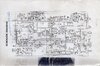
I looked at the schematics of the Memory 8012 (clear) and what I could find on your Dragon CB240N (fuzzy from Poland), the Memory drives the Final and Driver directly from the audio IC chip TDA2003 through D39, no transformer. Does your Dragon have the transformer or is without?

View attachment 48143

View attachment 48144

View attachment 48145
If without transformer, then the voltage being applied to the Collectors of the Final and Driver will be about 6v in AM (or about 1/2 of VCC).
If it has the transformer, then the voltage being applied will be 13v.

Do you have a better scan of the schematic for your CB240N ?

The reason why I ask is at 1/2 VCC, this means the output RF would be 1/4 of what it would be if full voltage through transformer.

Thanks for answering.

My Dragon does have the transformer installed, you can see it in this photo:

img_20211026_195304-jpg.48011


But if you look closely, I do not have the IC that is to the left of the TDA, like in your photo, the one that is bolted to the chassis.

Measuring the voltage at some point on the transformer can it indicate if there is a problem further away from the 2SC2314?

I do not have a better scan of my schematic, I did it years ago from the manual that I brought.
 
  • Like
Reactions: NZ8N
I have put the original 2sc2314 and the 3.8w is back.

I have measured the DC voltage after D11 and is 13.5v. in TX is 11.8v.

I attach a full resolution Schematic.
 

Attachments

  • Schematic dragon cb-240n.jpeg
    Schematic dragon cb-240n.jpeg
    4.8 MB · Views: 19
Last edited:
I do not have a Memory or Dragon radio to look at directly, and can only go by pictures and schematics provided by others.

Your schematic is a much better scan than the fuzzy one I found on the internet.

The picture I provided was of a Memory 8012 (found on Internet), and the IC next to the TDA chip is actually or should be a PNP power transistor Q55, 2SA1658, which I am going to guess provides full voltage to the Final and Driver when in FM mode, instead of 1/2 voltage in AM.mode.
 
  • Like
Reactions: thelonegunman
Yeppers - older design for the purpose of being able to even use FM too...

The Modulator delivers phase modulation too - Deviation is thru RV5

So even though full collector voltage - the CARRIER power is set up to be limited.

AM side is set for 1/2 - while FM mode is uses the AM "carrier" but it is deviation-driven - no envelope.

So you're limited to bipolar at the moment - but MOSFET can work - just carrier power is not present in which the little EKL devices can work independently - they will need a "trickle" or tickle-voltage to raise the MOSFET drive power.

A simple 10K or even 5K pot can do this...you'll need 3 parts - two to buffer and one to adjust...

upload_2021-11-3_7-51-25.png
This is from a filtered power source anywhere that is convenient - this supplies the trickle voltage.

1K buffer input keeps the supply side of this feeder from sagging - the 1K output keeps the EKL from interacting too heavily with this sourcing of power to just raise the drive voltage - 1K acts similar to a high impedance

You can try using a simpler divider - but how many parts are you going to make as possible combinations?

This gets you started and lets you experiment and adjust voltage to acheive certain effects of power and how much of the power can be developed before the audio and signal present - is pinched off.

upload_2021-11-3_8-15-5.png

Once you know the value - you can measure across to find a TOTAL resistance needed and make the divider permanent once you have set the right voltage. But Total amount to use - needs are thru a divider, not just one big resistor...

So you will still need two resistors - to find that value of both you measure from the aspect of the EKL requiring this power.

So measure from the output Buffer Resistor - to Source Buffer Resistor the pot has given you a resistor value of it's own divider two fixed with one wiper - to obtain this "ground" and "source" values thru itself.

We should have done this right from the start - it can save you time later when knowing you didn't have enough carrier power to make the EKL work as a stand alone - this gets you variable power.
 
  • Like
Reactions: thelonegunman
Yeppers - older design for the purpose of being able to even use FM too...

The Modulator delivers phase modulation too - Deviation is thru RV5

So even though full collector voltage - the CARRIER power is set up to be limited.

AM side is set for 1/2 - while FM mode is uses the AM "carrier" but it is deviation-driven - no envelope.

So you're limited to bipolar at the moment - but MOSFET can work - just carrier power is not present in which the little EKL devices can work independently - they will need a "trickle" or tickle-voltage to raise the MOSFET drive power.

A simple 10K or even 5K pot can do this...you'll need 3 parts - two to buffer and one to adjust...

This is from a filtered power source anywhere that is convenient - this supplies the trickle voltage.

1K buffer input keeps the supply side of this feeder from sagging - the 1K output keeps the EKL from interacting too heavily with this sourcing of power to just raise the drive voltage - 1K acts similar to a high impedance

You can try using a simpler divider - but how many parts are you going to make as possible combinations?

This gets you started and lets you experiment and adjust voltage to acheive certain effects of power and how much of the power can be developed before the audio and signal present - is pinched off.


Once you know the value - you can measure across to find a TOTAL resistance needed and make the divider permanent once you have set the right voltage. But Total amount to use - needs are thru a divider, not just one big resistor...

So you will still need two resistors - to find that value of both you measure from the aspect of the EKL requiring this power.

So measure from the output Buffer Resistor - to Source Buffer Resistor the pot has given you a resistor value of it's own divider two fixed with one wiper - to obtain this "ground" and "source" values thru itself.

We should have done this right from the start - it can save you time later when knowing you didn't have enough carrier power to make the EKL work as a stand alone - this gets you variable power.

Huff! I have read it 3 times but I am not able to understand what to do, my English is not good enough.

Could you please do a little schematic of everything that I should add and where?

Sorry to give you so much work.

P.S. I guess the 2SC2314s I bought are fakes, because none of them give power. But they do give hfE of 340, that's the strange thing.
 
  • Like
Reactions: Handy Andy
All you're doing is using a trim pot to FIND a resistor value - to make a divider where you put in the 10K - which seemed too much voltage so instead of just guessing I didn't want you to lose the IRF520 trying to find a working voltage to make the FET work.

I know this seems harder than it should be - it's not - all your doing is making up a "test jig" to make a variable voltage "source" so the EKL can work right.

The problem is in the AM to FM switchover - the level you can work with is different between the two.

So I'd like to know what is the voltage the EKL Parts makes in FM - then again, in AM mode
 
  • Like
Reactions: tecnicoloco
One thing I just wanted to post here to help others UNDERSTAND something regarding how a Tuning Tank and Bandpass works ...

You can turn a 4Watt output radio into a 350mW Transmitter - but simply removing the Final and Removing the Power Choke coil (like that on a Cobra 29 - L15). THEN SHORT BASE TO COLLECTOR PADS TOGETHER (form a solder bridged short) - the rest of the output then goes thru the tank circuit into the output network - you're running the radio on the Driver alone...

upload_2021-11-3_17-49-16.png
The critical part is L15 - your power choke to the COLLECTOR
You don't want to power the line - just disconnect the Final and remove
it's power...then SHORT BASE TO COLLECTOR to make this as a test jig
for signal generator or to work with designing EKL component to work MOSFET
you're replacing the Final with...​
 
  • Like
Reactions: tecnicoloco
Wow, I'm not getting anything. I think the time has come to assume that this is beyond me, and I must reinstall the original components. I'll keep this souvenir kit, and use the Superstar 3900.

This also implies that I appreciate all the help, I have learned things that I did not know. It is always good to grow.
 
well, I have reinstalled everything from the factory, and I have done a test. instead of the 2sc2078 I have placed a good 2sc1969.

The final power has been 3.8w again.

Either a component or setting fails before 2sc2314, or something discharges power to ground after 2sc1969.

I comment on this detail in case someone intuits what it could be. I think that the original problem was not the final transistor, but that there is another fault component, or bad potentiometer adjustment.
 
  • Like
Reactions: Handy Andy
Ok back to another question that was raised here earlier maybe 3 pages back has anyone tried the new 2030+ or the hg1969+ I'm here there is one of those out now as well from hg.
 
  • Like
Reactions: Shadetree Mechanic
I've experimented with the 2030+ in place of 520's and couldn't get them to work correctly. I called Eric Rutledge who at the time worked for Lewis to ask for data on the 2030+ and all he could tell was that they were a drop in replacement. That's all he had and I abandoned trying. They aren't a simple drop in.
 
Last edited:
I was asked by a few people how to do this mod, so I figured I'd just post it up.

Please don't copy and paste this mod to other sites/forums, but feel free to link to it.

Also applies to:
Uniden 78
Cobra 25 & Uniden 76 mod is similar, although you'll need to cross reference against the schematic.

1: change the final to a 2sc1969
2: change the driver to a 2sc2314.
3: change the electrolytic capacitor by the audio IC (C42, 1000uf) to a
3300uf, 16v.
4: Take a turn off the output tuning coil (see tuning coil note below)
5: Remove the AMC potentionmeter (VR4), and put a 1K resistor in it's place.
(only two connections are used on this pot, use those two connections
for the resistor)
6: add a 1K in series with D11.
7: Change R48 to a 33K ohm resistor.
8: Change R55 to a 10K 1 watt resistor.
9: change C37, and C68 to a .2 monolythic (this changes the A.F.
response on TX)
10: Now align the radio, start with the output coil, the the predriver
stage for peak output.
11: Tuning notes: Tune L17 for max with audio. Then, tune L23 for max output with audio, this will upset the radio's frequency. So, after L23 is set, adjust L24 to put the radio back on frequency.

Tuning coil note: If the radio says "made in China" on the back, you must remove 1 turn from the output tuning coil with the slug in it. If it doesn't then you may or may not have to. Count the turns, if it has 4, leave it alone, if it has 5, it's too many and won't tune, remove a turn. You may have to add a 68pf capacitor from the left terminal of the coil to ground, with the solder side of the board up. This method produces better results than just removing the tuning slug.

This mod will consistently produce output between 10-12 watts AVG and 45-50 watts peak. If I can find my video clips of Bird 43P power meter and spec analyzer I took after doing this mod, I'll follow up with those.
This link works. Do you happen to have the mod for IRF520's. I used to do the 520's back in the day (Like the '80's) so I'm in need of a refresher course. Thanks much.
 

dxChat
Help Users
  • No one is chatting at the moment.
  • dxBot:
    Tucker442 has left the room.
  • @ BJ radionut:
    LIVE 10:00 AM EST :cool:
  • @ Charles Edwards:
    I'm looking for factory settings 1 through 59 for a AT 5555 n2 or AT500 M2 I only wrote down half the values feel like a idiot I need help will be appreciated