• You can now help support WorldwideDX when you shop on Amazon at no additional cost to you! Simply follow this Shop on Amazon link first and a portion of any purchase is sent to WorldwideDX to help with site costs.

Cobra 29 LTD Frequency Mod (+Counter)

LeapFrog

Wielding Hanlon's Razor
Feb 15, 2016
1,709
903
123
Anchorage, Alaska
This is just the basic idea.
Credit should go to CBphreaker whos excellent work and kind mentorship brought these mods to light.

A.) The "Two Bands Mod".
{2 bands of 40 Channels using the stock "unmodifiable" PLL.}

B.) Super-Slider VXCO "extreme delta tune".
{Recommended to get to 27.xx5's when using the TX n-codes set of the Two Bands Mod.}

C.) Frequency Counter Mod.
{Working for Transmit, & Receive!
Compatible with: PLJ-6LED PLJ-8LED, Galaxy FC-347 frequency counters & Lesscomm 3 band pcb's.}

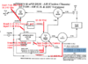
A.) Disconnect the 10.240MHz signal from the TX mixer. Build a 10.695MHz oscillator and inject this signal into the mixer instead.

Add a SPST switch (tied to ground) for the PLL T/R switch. We will be using one set of n-codes per band!

The TX n-code set will now get you a 40 channel band starting at 27.4100MHz or so, but channels will end on 27.xx0's and not 27.xx5's.


B.) Super-Slider VXCO Mod.
Disconnect the 5.12MHz signal going from the PLL to the tripler, build a 5MHz variable oscillator this signal will now go to the tripler instead. You can use a ten turn potentiometer to finely adjust the control voltage.


C.) Frequency Counter Mod.
For the PLJ-6LED, PLJ-8LED & Galaxy FC-347 counters to read during receive you must install the 10.695MHz oscillator. PLL will be using the receive set of n-codes in normal band. Sample your signal right at the mixer.

I haven't built this myself, but let us discuss

I failed to mention something, or explained incorrectly..
"Kintsugi"


-Leap
 

Attachments

  • diagram_text-29-phreak-osc.png
    diagram_text-29-phreak-osc.png
    172.6 KB · Views: 71
  • diagram_text-29-phreak-osc.png
    diagram_text-29-phreak-osc.png
    172.6 KB · Views: 55
Last edited:

You could use a Si5131 module or similar to generate the 5.XX MHz signal. It has three outputs so you could also use it to generate the 10.695 MHz, but that may need a bit of filtering since it's not going through a tripler coil.

User lbcomms over on Transmission1 has done some work in this area, mainly focusing on SSB radios. Same basic idea, though. Replace the 5.12 signal with one of your own. The SSB radios tend to already have a 10.695 MHz oscillator on board, so less to fuss with.
 
I did most of this to add a Glen 326G VFO to a Cobra 1000GTL, where the CB/PA switch became the internal PLL and channel selector when in CB mode, and the Channel display would blank out and the radio would be on the external VFO when in PA mode on the switch.
This was back when I worked at a CB shop in Newton Falls OH around 1984.
 
The first RX IF is 10.695MHz, and so the oscillator should be switched on during TX only; leaving on during RX results in a band-spam sandwich, with carriers appearing on every channel simultaneously.

This was the first version of the 10.695MHz oscillator pcb, I used the 612 because that IC would be the audio injection point for a DSB signal.

The "updated" PCB uses a 2n3904 (even cheaper). The crystal was raised up to show the frequency when in fact it can be lying down for an ever smaller more compact footprint.

There are no wires to hook up. Just a simple cap move and the unit plugs right in and put a switch on D15 to ground.

I have also thought about using 14.91MHz crystals in a VXCO circuit and I wonder if they will pull at least 5Khz to make a 40 high and 40 low which using the 14 would be 26.515 - 27.405. Sadly with only 5khz pull the "A" channels are out of reach but being of the 5s would result in two usable bands H/L. using the stock PLL. I think it would possible to make it switch "automatically" on the H/L switch so no 5KHz twist of the the slider needed. But I don't mind really.

The first VXCO I made for the Cobra 1000 used 5Mhz (cheap ass) microprocessor crystals; using 5 in parallel I was able to get ~12 khz up and down.

The freqs are out of wack with the channel selector, but who cares there is a freq counter.
 

Attachments

  • 10695_612.jpg
    10695_612.jpg
    3.5 MB · Views: 47
Last edited:
  • Like
Reactions: NZ8N
I know this is an old post wondering if there is a schematic for the crystal oscillator would like to build one. thanks
 
I know that but was looking for a single xtal oscillator to experiment with. I like how small it is also I have the s-kit single xtal board that also works in the 29s. for single board mods I have all my boards made in China much cheaper then here in the States. So looking for something small/compact and this looks small.
 
Leap Frog made his 10.695 oscillator on perfboard. I did similar (perfboard) to a Cobra 1000GTL in/around 1984 for a customer who wanted a Glen 326G VFO installed https://www.cbtricks.com/miscellaneous/vco/glen/index.htm . I put the Glen on the CB/PA switch, when in CB mode, the regular PLL and channel display worked. When in PA mode, the Channel display and PLL/VCO shut off, and the Glen took over.
 
Maybe Leapfrog will see this and chime in with a schematic and parts he used.
Always looking for something to keep me busy. LOL
 
  • Like
Reactions: LeapFrog
I saw this on YouTube I think it was. And their was a second part where the 5mhz signal came from a board using like 5 5mhz arduino crystals and provides a slide thing to get the a channels.

Kinda neato.
 

dxChat
Help Users
  • No one is chatting at the moment.
  • dxBot:
    Tucker442 has left the room.
  • @ BJ radionut:
    LIVE 10:00 AM EST :cool:
  • @ Charles Edwards:
    I'm looking for factory settings 1 through 59 for a AT 5555 n2 or AT500 M2 I only wrote down half the values feel like a idiot I need help will be appreciated