Maybe doing a continuity check on the mic audio line and ground line, with the mic open and the radio open, checking from the mic, thru the mic connector, into the radio for continuity. Ive experienced poor or no connections thru mic connectors before (even antenna connectors).

You are using an out of date browser. It may not display this or other websites correctly.
You should upgrade or use an alternative browser.
You should upgrade or use an alternative browser.
-
You can now help support WorldwideDX when you shop on Amazon at no additional cost to you! Simply follow this Shop on Amazon link first and a portion of any purchase is sent to WorldwideDX to help with site costs.
-
A Winner has been chosen for the 2026 July 4th Retevis RA89R Giveaway! Click Here to see who won!
Did I miss a memo or something??? (GE 3-5811B related)
- Thread starter guitar_199
- Start date

Okay... I only woke this one up to let you all know the final answer. The final act occurred today (Sat, April 4).
The original complaint of low modulation was really indeed the two factory resistors that were swapped in their locations. And yes... it cam from the factory that way. The solder had not been touched. In addition... one of the two swapped resistors was a 5.6k in the radio... BUT it is a 1K on the schematics. The way this is configured:
With the 5.6K and 33K swapped the mic signal coming in would be severely attenuated. Add to that.... the one that the schematic says should be 1k but is actually a 5.6K .... would kill the mic audio even MORE!!!!!!
Needless to say, I put the 33K back where the 33K should be and I put a 1K where the 5.6 K would have been.... NOW it matches the schematic!!!
The modulation did come up as high as about 63% (measured on a scope)...but any pushing of mic audio beyond a certain point caused a very ugly and spiky distortion in the audio waveform. Also the AMC adjust had surprisingly little effect on the audio level.
THAT was tracked down today. A bad C4 (220uF 16v) that was the main output cap out of the audio amp.
What is weird..... when I removed the old one I tested it on my component tester:
in ONE direction... it showed a 26 pF cap.
turn it around to the OTHER direction.... it showed a 47 uF cap.
This is weird behavior for an electrolytic cap... especially a 220 uF one!!!!
The new cap tested 227 uF in both directions so I felt good about that.
Put it in and the modulation envelope was beautiful!!!!
AND.... NOW the AMC control worked.
Set the AMC for about 97% and now I can yell into the mic and not clip or pinch.
So, at the end of the day, all is good!!!!!
XMT: about 3 watts carrier, fwd mod present (dont have a peak reading meter!)
RCV: I could hear the tone WELL down to -120 dBm and that is as low as my 2040 goes on the dial.
So..... ignore my original starting topic!!!!!
It is up and alive.
Too damn awesome! And a GREAT job you kept at it! I was wanting that exact radio a couple years ago, but was afraid to buy it as it isnt one that reads a "power mic" in the label in the front....
Now I will keep an eye out for the radio you fixed, and do the necessary changes to it.") I always dislike I have to yell into a mic to get it to modulate.
I always dislike I have to yell into a mic to get it to modulate. 
Now I will keep an eye out for the radio you fixed, and do the necessary changes to it.
I always dislike I have to yell into a mic to get it to modulate. Just like that, found one in decent shape (At least on the pictures) on eBay for a whopping $25 free shipping (not including taxes.) Purchased.
With that being said, was a bad capacitor the main culprit this entire time? would leaving the resistors alone still be ok after a recap?
With that being said, was a bad capacitor the main culprit this entire time? would leaving the resistors alone still be ok after a recap?
Last edited:
Now I am on the hunt. The powered mic versions of the General Electric radio can sound good, but one has to basically be up very close to the mic. The one I do have now is a GE 3-5813B.
I dont have a schematic on hand or know what exactly I am looking for, but I wonder if it has the same issue that you had as far as the schematic calling for a 1k resistor vs the 5.6k one you found that was in there. Maybe that is what's going on with this one?
Ill ask over in the appropriate thread for a Schematic.
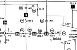
The actual "first" problem I found is covered in the MicCircuit image below.Just like that, found one in decent shape (At least on the pictures) on eBay for a whopping $25 free shipping (not including taxes.) Purchased.
With that being said, was a bad capacitor the main culprit this entire time? would leaving the resistors alone still be ok after a recap?
RCV was great to the ears to begin with.
XMT carrier was great on the scope and spectrum analyzer.
But modulation was "non existent". Seriously.... I would say no more than 5%.
R58 (33K) and R59(5.6K) were swapped on the board from the factory. The solder was original. The 33K was in R59's spot and the 5.6K was in R58's spot. THAT MISTAKE ALONE accounted for super low mic audio. And then... on the schematic R59 is a 1K and the factory put in a 5.6K which would reduce it SOME after they were put back in the right places. SO I also changed out the 5.6K for the 1K indicated in the schematic.
After THAT I got the modulation up to about 63% measured but if I pushed it ANY HARDER the modulation envelope (audio) broke into a horribly jagged/sharp/spiky distortion on the scope.
THAT problem was C94 (220 uF 16v). When I pulled it out and put it on a parts checker.... ONE DIRECTION was 26 pF.... the OTHER DIRECTION (flipped it physically) measured 47 uF!!! The new cap measured 227 uF no matter which way I put it in!!!!! So I soldered it in and the deed was done.
After that.... the AMC control let me tweak the measured modulation up to about 97% and I just stopped there. But that modulation envelope was sweet looking. Speech looked good on the scope and, as I said, barking into it really hard would not make it distort!!!
Attachments
That is pretty neat! Do you know what Cybernet board number is in that radio? I was going to try and compare it to other radios.The actual "first" problem I found is covered in the MicCircuit image below.
RCV was great to the ears to begin with.
XMT carrier was great on the scope and spectrum analyzer.
But modulation was "non existent". Seriously.... I would say no more than 5%.
R58 (33K) and R59(5.6K) were swapped on the board from the factory. The solder was original. The 33K was in R59's spot and the 5.6K was in R58's spot. THAT MISTAKE ALONE accounted for super low mic audio. And then... on the schematic R59 is a 1K and the factory put in a 5.6K which would reduce it SOME after they were put back in the right places. SO I also changed out the 5.6K for the 1K indicated in the schematic.
After THAT I got the modulation up to about 63% measured but if I pushed it ANY HARDER the modulation envelope (audio) broke into a horribly jagged/sharp/spiky distortion on the scope.
THAT problem was C94 (220 uF 16v). When I pulled it out and put it on a parts checker.... ONE DIRECTION was 26 pF.... the OTHER DIRECTION (flipped it physically) measured 47 uF!!! The new cap measured 227 uF no matter which way I put it in!!!!! So I soldered it in and the deed was done.
After that.... the AMC control let me tweak the measured modulation up to about 97% and I just stopped there. But that modulation envelope was sweet looking. Speech looked good on the scope and, as I said, barking into it really hard would not make it distort!!!
From what I understand, most Cybernet boards need a power mic behind it. Otherwise, there is almost no modulation without literally yelling up close into the mic before it even goes. Talk in a normal voice and about 2 inches away from the mic, it barely can be heard and only a watt or so swing. With a power mic behind it, it goes to what I had the AMC set to, which was 8 watts. (It might be a bit much but otherwise sounded good on the other radio with no distortion.)
Last edited:
Don;'t know the board number and the SAMS doesn't show it....That is pretty neat! Do you know what Cybernet board number is in that radio? I was going to try and compare it to other radios.
From what I understand, most Cybernet boards need a power mic behind it. Otherwise, there is almost no modulation without literally yelling up close into the mic before it even goes. Talk in a normal voice and about 2 inches away from the mic, it barely can be heard and only a watt or so swing. With a power mic behind it, it goes to what I had the AMC set to, which was 8 watts. (It might be a bit much but otherwise sounded good on the other radio with no distortion.)
I'll have to crack it back open and take a look......
Well... for one... there is not a single mic audio amplification stage before the audio chip. Literally.... passive components.... no gain....... anywhere in the path on the 3-5811B. But after I set the AMC.... it seemed very sensitive!!!!
Good to know.Don;'t know the board number and the SAMS doesn't show it....
I'll have to crack it back open and take a look......
Well... for one... there is not a single mic audio amplification stage before the audio chip. Literally.... passive components.... no gain....... anywhere in the path on the 3-5811B. But after I set the AMC.... it seemed very sensitive!!!!
It will be fun to see how the radio does once it comes here later this week. I will for sure report back on my findings.PTBM090C0X maybe? The non amplified Cybernet AM PLL02A boards are mostly the same.That is pretty neat! Do you know what Cybernet board number is in that radio? I was going to try and compare it to other radios.
From what I understand, most Cybernet boards need a power mic behind it. Otherwise, there is almost no modulation without literally yelling up close into the mic before it even goes. Talk in a normal voice and about 2 inches away from the mic, it barely can be heard and only a watt or so swing. With a power mic behind it, it goes to what I had the AMC set to, which was 8 watts. (It might be a bit much but otherwise sounded good on the other radio with no distortion.)
edit: https://www.hvde.nl/electronica/tx/Cybernet/Cybernet_nl.shtm
I promise I will double check it.... but it will take a day or two!!!!!!!!PTBM090C0X maybe? The non amplified Cybernet AM PLL02A boards are mostly the same.
edit: https://www.hvde.nl/electronica/tx/Cybernet/Cybernet_nl.shtm
I am "promised to the Missus" for some tasks here at home..... and THIS is how i stay married for 52 years!!!!!!!!!!
I promise I'll check!!!
You are A ok.I promise I will double check it.... but it will take a day or two!!!!!!!!
I am "promised to the Missus" for some tasks here at home..... and THIS is how i stay married for 52 years!!!!!!!!!!
I promise I'll check!!!
No rush. I was messing with a SBE Sidebander II radio. Kinda neat. AM seems to be solid, but SSB struggles to get much modulation without yelling into the mic. It was included in a trade a couple years ago. Not in dire need to get it going lol.My GE 3-5811B should arrive tomorrow. No worries.
"The Wife always comes first before the radio." (Rest in Peace my Elmer K7NNV since 2022. He told me that.)Good catch. I'm so used to it that I often forget to mention it. I can't count the number of GE AM radios I've picked up for nothing and simply replaced the RP diode ... I'm a huge fan of the Cybernet TX circuit of this vintage. I'll check my notes for the Hot rod mod as well as a bit RX tuning. Do keep in mind that the TA7205P may very well be rated at 5W plus audio but it's THD at max output is like 8%. More later...Just got the radio in. It is the PTBM050C0X. Didnt realize the power connector on back has the polarity different then that of a standard Cobra power cable. I will swap the wires around inside the radio so one doesn't burn up the radio.
...or now. I didn't post this and came back with a cup of , whatever, and decided to finish. Most will be links to this site with brief notes.
First is a lesson in less is more.
Andy , since you said please...
I have a unique voice. You won't notice it via most telecom and most people even miss it in person. An audio spectrum analyzer doesn't miss it . I have a well defined hole in the frequencies my voice box produces. There is little or nothing between 850 and 1300 Hz . We had an FM broadcast station in High School that turned up the peculiarity. I have several voices that range from shock jock to late night DJ and some character voices in between but my normal relaxed voice has always had that hole.
So when I had a hot rod station on 11m it consisted of a...
With the understanding that just finding a "real" 2SC1969 is an adventure in itself. I also failed to mention that the current paht to the final and driver had much improved conductor traces as well as much heavier gauge chokes. A heatsink was also added to the back of the radio.
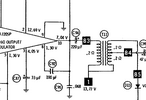
 If you understand DC voltage dividers already this will be easy. If you understand AC voltage dividers Just swap c42 and c43 .If you don't want to understand Just swap c42 and c43....
Next Take out the driver Q4 and the final Q5. Save the driver in some safe place you won't be able to find it later and put the final in the driver hole. Now put the 2SC1969 in the final hole. Now retune. I've given up on replacing the predriver as it's just unnecessary. About the retune. It's a little soft, meaning twisting stuff gives little else than an expected increase. However it's best done with scope as the additional gain will occasionally give some unintended results. As I was saying in the linked post less is more. 3.8W-4W and swing for the fences is okay, ish, but @nomadradio has a peel and stick device that could be easily perverted to the task of carrier control. Then the TA7205P. It can't keep up so don't try. Just be happy with single digit THD most of the time and the possibility of a pit more on the peaks. A scope will iron it out in a minute.
Just got the radio in. It is the PTBM050C0X. Didnt realize the power connector on back has the polarity different then that of a standard Cobra power cable. I will swap the wires around inside the radio so one doesn't burn up the radio.
The AVR and ALC are not what they seem. Learn how to read a schematic.
Where did I put that cup of .....?
Appreciate the information. Does it still yield results by swapping C42 and C43 without replacing for a 1969 final? I just dont have a way to retune if I do swap out for a 1969.
I really really need to learn to read a schematic and not be instantly confused...
I really really need to learn to read a schematic and not be instantly confused...
dxChat
- No one is chatting at the moment.