• You can now help support WorldwideDX when you shop on Amazon at no additional cost to you! Simply follow this Shop on Amazon link first and a portion of any purchase is sent to WorldwideDX to help with site costs.

Direct injected galaxy DX55V wattage problems

Center pin of the Predriver, there are two - which of the two? TR46 and TR45...
upload_2020-10-11_15-44-35.png

If its' towards the Driver, then look for bad parts, soldering issues in-between Predriver and around the Driver...
 
  • Like
Reactions: That_guy_in_wv
Tr45's center pin which I believe is the collector is the one with high voltage/millamps. Tr46 is the RF amp and buffer, again same same but different, but tr46 shows fine when tested. Pretty much does the same thing as tr45. I'll check around the final section to see if I can find any problems.
 
I finally got time to do some soldering, I changed the caps leading from the pre-driver and driver final and caps in the circuit leading the the final. I also reflowed the solder around the finals and parts leading to the finals and driver, still same problem can turn rf power up and won't turn back down. I left the mic amp circuit out of line so we don't have to mess with it further. Any other suggestions handy Andy?
 
If you have time - did you also check around the SO-239?

When I have to track down these messes, I find that I have to replace caps that drift off by simple substitution, but in this kind of matter, the effort has to go to assembly - for as one injects the audio - that path is the one that is placed under the most stress from errant voltages and currents that exist OUTSIDE the environment.

You asked about caps. I do know that some caps are not compatible because of their design is too inductive for the part they play a role in, you need a proper part.

That is where the "85C" or 105C ratings come into play, for the materials used in the cap are different between the two to a point that RF can interact poorly

Sometimes, the best luck arrives by removing one part and trying to see if the conditions change - if it does change that wasn't the part, it ADDS to it, so put it back in there, and the next part along the chain needs to be swapped out and tried again.

I do this to the caps in the strip, I find that if the cap was bad, the condition would not change severely - in some instances the radio recovers to a point to tell you that "this section is the culprit."

Other points I work with...

You say, that the injection point and the external parts - seem to work ok, the radio isn't.

So substitution may be the only method left to swap out the parts.

Since you disconnected the Mic amp - and the problem still exists - the main thrust I'd be looking into is the disassembly and reassembly issues you may have had to deal with when you did the injection mod - of Final, Driver and any hardware that got pulled off or shifted to make room for the install.

You say you reflowed the solder, but did you double check the insulator pads and hardware in that area.

But something doesn't jive right, I've seen dried out goo that has caused similar problems - a simple remove clean off and reapply and reposition install their the Driver and or Final and we're on the Air again.

The condition started when you were at your friends house, then the subsequent check, recheck, but one thing I haven't heard too much from you about is the Output Network when you took your radio over to their place and tried it, that's when the problem started.

So that means three points of note, Mic amp, Injection point and mods, and the antenna you hooked it up to - you say things are fine with their radio - it's yours that has the condition.

So I'd remove - break the injection point - disconnect and leave that part, as well as the Mic amp, out, then see if power condition is there - if it is, it's past the injection point and pertains to the TX strip AM Regulator / RF Power and parts around it.

I didn't say it was going to be easy...
 
Last edited:
  • Like
Reactions: That_guy_in_wv
Thanks for the info and reply Andy,

Ok so the install of direct injection was easy just had to remove C191 and put the hot (center) of the audio to the hole closest to the center of the board at C191 through a 10uf 25v cap (mod said it didn't matter tantalum or electrolytic) with the positive in the hole from c191 closest to the center of the board, also said to change C190 to a 300uf at 25v but that was all the mod was for injecting audio. Two components changed so far is all. I replaced the final and driver both and cleaned the old ceramic insulators and used new heat sink compound sparingly on both when installing them back. I'll check out the circuit leading to the so239 and see what might be bad if anything is. The radio worked fine here and I still use my 55 with my setup, but this radio after being used on my buddy's computer isn't the same as when it left, so far 2 radios he had used a 55v-Di and 33hml-Di has both done the same thing, with the audio cord unhooked from his desktop or my laptop on them both you can turn the rf power knob up and down while still keying and adjustments work fine, but as soon as the audio cord from my laptop, phone or his desktop is inserted the wattage cannot be turned down. Both of us use IMAX 2000 antennas, but even on my dummy load it does the same thing since it happened.
 
So far I only have a plug mounted to the back for a headphone plug, the hot is going to center and into the 10uf 25v caps negative at C191, ground from the plug on the headphone plug I installed is going to ground on the potentiometer at L5 closest to C191 that's all I did and would still be working here if not hooked up at a friend's lol. We used voice meeter eq and run our audio cords from the headphone outputs from mine and his computers to the headphone ports I installed on the back of the radios.
 
Another thing I wanted to let you know is I rechecked tr51's voltage on center pin (collector) and i am getting a 3.2v reading and the voltage is dropping the longer i key the radio down (over about 15 to 20 seconds) the voltage dropped down to around 2v before I unkeyed the radio. RX voltage was the same B12.6-C3.2-E11.9 but wasn't dropping without being in TX mode.
 
Where I used L5 for board ground for the audio cord it got me thinking about the AM/FM being "active" at the same time like someone already has said. Would a short to ground through L5's potentiometer cause this problem. L5 is the FM detector.
 
Tried FM and I'm showing forward swing which shouldn't be happening, same on FM wattage can be turned up and will not go back down. Frequency Modulated is completely separate from amplitude modulation, only AM should show forward swing. It's almost like I never flipped the AM/FM switch at all. Never mind i about threw a cup of coffee across the room when I flipped the switch to FM, volume was turned up way too high. It's definitely switching RX over to FM but I still have swing on FM.

sorry for all the long post but hopefully this info might help to understand what the problem is better. Thanks again for the help any info is appreciated a bunch.
 
Ok so to clarify my last post, the radio isn't transmitting FM on FM only receiving FM on FM and still transmits the AM signal with the mode switch on FM. With another radio on close and with the mode switch on both radios on FM the di 55v is transmitting AM on FM mode. But we might have disabled it? I'm not sure my 55v that does work will transmit FM on FM never tried it yet.
 
Ok so to clarify my last post, the radio isn't transmitting FM on FM only receiving FM on FM and still transmits the AM signal with the mode switch on FM. With another radio on close and with the mode switch on both radios on FM the di 55v is transmitting AM on FM mode. But we might have disabled it? I'm not sure my 55v that does work will transmit FM on FM never tried it yet.

Nice, ok then let's slowly put the radio back together.

But again look for that oscillation. we may have missed a step earlier. Went back thru a lot of posts here. TR34 and TR53 work together.

When you switch to FM, the C191 cap, the side that goes to the MIC amp - goes high - gets straight 8 volts ON THE AUDIO Side, not the AM Regulator - so you'd be able to adjust AM power this way, and FM power too, so to see AM and FM working the same power level - kinda brings me back to that front panel and it's switches again.

So if you switch AM to FM, you quench C191 with a lot of DC to wash out Audio... C187 keeps it from going back into the Mic amp.

The audio then re-routes to the new path of least resistance...

The PLL then sees a signal from the MIC amp - as an AUDIO signal. Thru C126, R160, Balances with R123.

This was part of the reason for removing TR53 to see if the envelope control was even there. FM works, but you have the AM component - so the 8 volts the Mic amp line sees at C191 - then tells us that it "quenches" that line - if you notice, there is another cap that is UPSTREAM - towards the Mic Amp C187 - that blocks the 8 volts from that AM/FM PA switch from damaging the output and trigger false positives on the RX/TX lines too.

This method of holding the line high - silences the AM audio from ever getting to the AM regulator. It washes, swamps it out - so the only place it can go now, is to FM mode thru C126 (another cap that can leak)

Pulling the Mic amp connection was another reason, we have to remove any possible loops that may cause this condition.

We've established it is.

You have help isolate this problem to traced to the switch your AM/FM PA one - this may be the very problem you have.

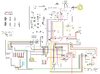
Locate S502...I think you have this board...
upload_2020-10-27_8-58-28.png

Take it or leave it, this may help...

Or C126 as leaking the audio signal to the FM side. This can cause a loop condition too...

IF that switch is bad, then the problem with the external was related in a way to this failure.

If the FM side cap - C126 - if its; leaky, or that lines been worked on - (D31 and D32) the loop can form from the FM side "awakening" when it shouldn't.. There is no "switch" to stop it except AM and FM and the PA modes the S502 (and all it's poles) sends voltage arriving to C191 from that switch and the other pole of the switch that also TURNS OFF(ON) the FM RX IC and Uses D31 and D32 to allow for, or stop (quench) Audio from going to the PLL and ringing with the Varactor. BUT THAT IS ON (8 volts all the time) in RX/TX modes

To take out TR53 and TR34 shows us the loop problem is not there...you can put them back in, we'll have to go at this another way if this condition still exists.
 

Attachments

  • Galaxy55VIUnterconnection.jpg
    Galaxy55VIUnterconnection.jpg
    832.3 KB · Views: 1
I'll replace tr53, tr34 and change out the AM/FM/PA switch and check C126, D31 and D32 and get back with you handy Andy, that's alot of good info on am/fm modes thanks. Glad there's a place like this we can put heads together to figure problems like this out.
 
Had an idea so I got the 33hml DI out because it's the same way weird wattage can be turned up but not down so I'm working on a theory....so I put the radio back together factory cap values and regular radio. Radio works fine it only does this weird wattage that won't go down when turned up when direct injecting through C191. Nothing in the other hole of c191 is why fm does not activate. I also replaced the parts from before in the 55v other then the cap at c191 it's still wired for direct injection but still has the same problem. Replaced d31,d32, c126 and tr53 and tr34 no change.
 
AM/FM/PA switch is fine works on all 3 modes when put back to non direct injected stock radio. What are your thoughts about the ground at L5 tuning pot, my ground wire at L5 runs up to the audio plug on the back which touches case ground shorting case to board ground (plug is metal threaded with metal nut) I couldn't find a plastic thread headphone input. Even removing the plug from case ground shows the same symptoms now though.
So would that have shorted something on L5's pot through board ground or shorted something through the case ground. Whatever you can think of I'll try first just wondered about that since I've already changed everything on the circuit leading from C191 to the audio amps to the finals.
 
L5 - hmmm

You know, those can covers can be removed...

Might want to see if there is something going on - right now? I'm really out of ideas...

The only possible way this could cause issues is if the coil in the case got deformed or the coil itself changed - in what way? You'd have to take it out to look at it.

I'd try removing the L5 and inject mod, and see if this comes back - if it happens again.

The IF coil is for the "discriminator" side - runs alongside the IF to "ring out" audio from a steady known IF signal and the input IF (Of FM captured signal) arriving - the discrepancy, is the audio. L5 Peaks this effect.

But in the meantime - swap the L5 - take out the inject at the moment - put another L5.

Now why? Well, if soldering the case can was the problem, this is an IF coil - if there were problems with the coil winds - they usually show up when the radio get's built - like just after the waveflow soldering. If L5 had some "extra" work done to it or if L5 - being s "strict" IF can - If work done to it deformed the core of the coil - it becomes unpredictable untunable.

The issue with IC2? Well, grounding loops, remember that this can works IC2 - hope it did not damage the IC from input because the power pin needs to have power applied first, so if you have FM - this tends to say we dodged a bullet and the radio works, but what I cannot say if if there are issues with , in and around IC 1 from this.

But if a grounding issue came up - this area is very VERY fussy about Detector and IF - the sensitivity and regenerative effects tend to couple together.

The problem may not be with L5 - but if you can re-LOCATE your ground to say that Power Choke in the rear and route you line carefully - to C191 location The issue though right now, is what damage was done.

Knowing it's L5 - woof, this may be anything from Detectors onto any IF source looping back thru the inject mod.

Ok, for next time, when doing a Direct Inject, don't use any of the RF/IF strip for ground - use the power choke case to board flanges that solder and hold that filter in place.
 

dxChat
Help Users
  • No one is chatting at the moment.
  • @ Wildcat27:
    Hello I have a old school 2950 receives great on all modes and transmits great on AM but no transmit on SSB. Does anyone have any idea?
  • @ ButtFuzz:
    Good evening from Sunny Salem! What’s shaking?
  • dxBot:
    63Sprint has left the room.
  • dxBot:
    kennyjames 0151 has left the room.