About a month ago, I decided to purchase an Elecraft K3 kit, sight unseen. Actually, I had seen the rig at Dayton, but I hadn't given it much attention. After reading a few very technical reviews of the Elecraft K3 touting the technical specs and merits of this very interesting rig, as well as talking extensively to a long time K3 user (and field tester for Elecraft), I decided to take a chance on a rig I had never actually touched. If you pause to think about it for a minute, this is actually how most ham operators probably make purchase decisions that don't live near a major ham radio store of some type. Now that I have the rig in place, it's time for a long term review.
While you're researching the K3, you will undoubtedly come across the detailed technical Clifton Labs series of articles. They are excellent and should be read in detail if the technical specs are your thing. The articles can be found here: Elecraft K2 and K3 Transceivers. My purpose with this review is not to comment on Clifton's findings, but to give a more general functional and practical review that more ham operators can identify with. If you have any questions or opinions of your own, please feel free to ask or comment.
The Build
If you would like to follow along with the build process, I've put together detailed photos of the major steps here: http://www.worldwidedx.com/hf-bands-hf-rigs/68225-elecraft-k3-build-photo-diary.html. To sum it up, the build process is fairly straight forward. It isn't something that you should be afraid to try and it will familiarize you with the major components should you decide to purchase upgrades later. An additional plus for building the kit yourself is that Elecraft occasionally comes out with updates that require you replace or modify various component boards. If you've already experienced the build process, disassembly and reassembly will be a snap. The primary issue that you need to be careful about with the build process is making sure that you're using all the proper length machine screws and washers at each step. I feel that there are a few places where Elecraft should take some simple steps to ensure that you're using the correct screw lengths, but they don't, and you've been warned.
Aesthetics
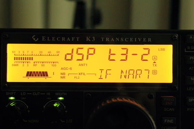
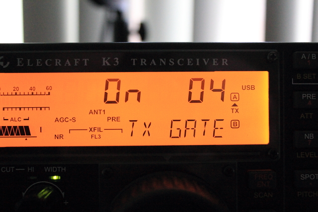
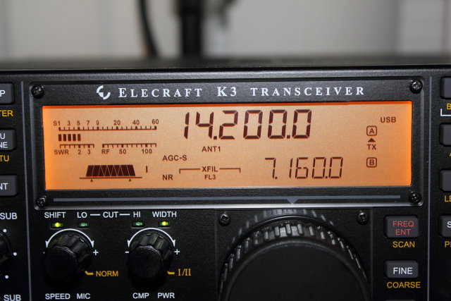
The K3 interfae can probably best be described as utilitarian but simplistically elegant. The LCD display is smaller than the higher end Icom, Yaesu, and Kenwood rigs, but larger than some of the more entry level rigs. While the display is small (the whole rig has a small footprint), it does a remarkably good job of showing you all of the important information at one time. The digital S meter, SWR meter, TX power, ALC, compression, VFO A & B, mode, antenna selection, and filter selection are all easily visible. Here is a pic of a typical display:
One of the reasons that the display is able to be smaller than other rigs is because the K3 does not make use of soft keys that change function depending on the screen. This type of user interface is typically found in the Icom rigs. The advantages of this approach are that learning the functions and usage of the various buttons and knobs is fairly easy; you don't have to remember any complex menuing system. However, since the K3 is truly a Software Defined Radio, the lack of soft keys might actually be limiting to the future growth potential for new features.
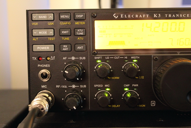
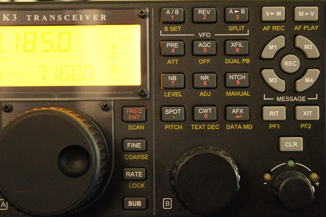
Most buttons have at least two functions, and some have three. The function printed on the button is the function that is activated by tapping the button, while the label printed below is activated by pressing and holding the button. If the button you're pressing activates a variable settings, VFO A or B will adjust the setting. When there are more than two adjustments necessary, Tapping the 1 or 2 button will activate the other toggle adjustments. It may sound a little complicated, but once you understand the operation, it really is easy to remember because it is consistent throughout all operations. Here are a couple of pics of the main front panel and the various functions:
Front left:
Center controls:
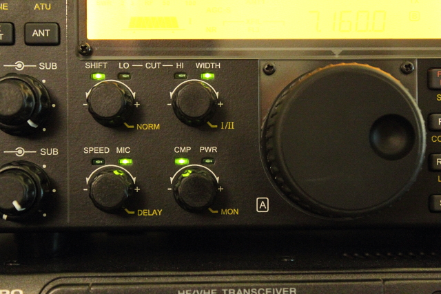
The center controls are examples of knobs with three functions. You toggle from the left side labeled function to the right side by pressing the knob quickly. You adjust the setting by rotating the dial and activate the third setting by pressing and holding the dial.
Right side:
Standard Interface Features
The K3 comes standard with a built in, isolated sound card interface. By plugging in a basic stereo 1/8" and another mono 1/8 cable to your computer you can easily use sound card modes without purchasing or building any type of external interface. Because the built in sound card interface is RF isolated, you don't have to worry about nasty ground loops causing ground hum problems. The RS232 is a standard serial interface used for rig control, memory programming, and firmware updates. The ACC port provides inputs and outputs that include band data, PTT, Transverter control, external ALC, and other functions. The other ports on the bottom of the rear are standard ports for a CW paddle, key, PTT, and amplifier keying. A pic of the rear standard interface is shown here:
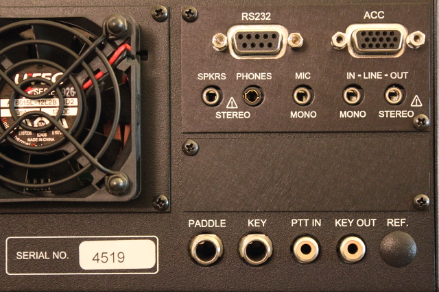
The blank panel directly below the standard I/O panel is the location of the optional RX antenna input/output, transverter I/O, and IF Out that you would use with panadapters.
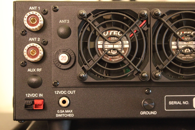
This left rear pic shows the two standard antenna ports (ANT 2 comes with the optional auto tuner) and the location where the optional sub receiver port and 2 meter port would be. The power adapter is a standard Anderson Power Pole adapter.
Now that I've covered the major physical attributes, the next topics will cover actually using the rig. More to come...
While you're researching the K3, you will undoubtedly come across the detailed technical Clifton Labs series of articles. They are excellent and should be read in detail if the technical specs are your thing. The articles can be found here: Elecraft K2 and K3 Transceivers. My purpose with this review is not to comment on Clifton's findings, but to give a more general functional and practical review that more ham operators can identify with. If you have any questions or opinions of your own, please feel free to ask or comment.
The Build
If you would like to follow along with the build process, I've put together detailed photos of the major steps here: http://www.worldwidedx.com/hf-bands-hf-rigs/68225-elecraft-k3-build-photo-diary.html. To sum it up, the build process is fairly straight forward. It isn't something that you should be afraid to try and it will familiarize you with the major components should you decide to purchase upgrades later. An additional plus for building the kit yourself is that Elecraft occasionally comes out with updates that require you replace or modify various component boards. If you've already experienced the build process, disassembly and reassembly will be a snap. The primary issue that you need to be careful about with the build process is making sure that you're using all the proper length machine screws and washers at each step. I feel that there are a few places where Elecraft should take some simple steps to ensure that you're using the correct screw lengths, but they don't, and you've been warned.
Aesthetics
The K3 interfae can probably best be described as utilitarian but simplistically elegant. The LCD display is smaller than the higher end Icom, Yaesu, and Kenwood rigs, but larger than some of the more entry level rigs. While the display is small (the whole rig has a small footprint), it does a remarkably good job of showing you all of the important information at one time. The digital S meter, SWR meter, TX power, ALC, compression, VFO A & B, mode, antenna selection, and filter selection are all easily visible. Here is a pic of a typical display:
One of the reasons that the display is able to be smaller than other rigs is because the K3 does not make use of soft keys that change function depending on the screen. This type of user interface is typically found in the Icom rigs. The advantages of this approach are that learning the functions and usage of the various buttons and knobs is fairly easy; you don't have to remember any complex menuing system. However, since the K3 is truly a Software Defined Radio, the lack of soft keys might actually be limiting to the future growth potential for new features.
Most buttons have at least two functions, and some have three. The function printed on the button is the function that is activated by tapping the button, while the label printed below is activated by pressing and holding the button. If the button you're pressing activates a variable settings, VFO A or B will adjust the setting. When there are more than two adjustments necessary, Tapping the 1 or 2 button will activate the other toggle adjustments. It may sound a little complicated, but once you understand the operation, it really is easy to remember because it is consistent throughout all operations. Here are a couple of pics of the main front panel and the various functions:
Front left:
Center controls:
The center controls are examples of knobs with three functions. You toggle from the left side labeled function to the right side by pressing the knob quickly. You adjust the setting by rotating the dial and activate the third setting by pressing and holding the dial.
Right side:
Standard Interface Features
The K3 comes standard with a built in, isolated sound card interface. By plugging in a basic stereo 1/8" and another mono 1/8 cable to your computer you can easily use sound card modes without purchasing or building any type of external interface. Because the built in sound card interface is RF isolated, you don't have to worry about nasty ground loops causing ground hum problems. The RS232 is a standard serial interface used for rig control, memory programming, and firmware updates. The ACC port provides inputs and outputs that include band data, PTT, Transverter control, external ALC, and other functions. The other ports on the bottom of the rear are standard ports for a CW paddle, key, PTT, and amplifier keying. A pic of the rear standard interface is shown here:
The blank panel directly below the standard I/O panel is the location of the optional RX antenna input/output, transverter I/O, and IF Out that you would use with panadapters.
This left rear pic shows the two standard antenna ports (ANT 2 comes with the optional auto tuner) and the location where the optional sub receiver port and 2 meter port would be. The power adapter is a standard Anderson Power Pole adapter.
Now that I've covered the major physical attributes, the next topics will cover actually using the rig. More to come...
")