
You are using an out of date browser. It may not display this or other websites correctly.
You should upgrade or use an alternative browser.
You should upgrade or use an alternative browser.
-
You can now help support WorldwideDX when you shop on Amazon at no additional cost to you! Simply follow this Shop on Amazon link first and a portion of any purchase is sent to WorldwideDX to help with site costs.
-
A Winner has been chosen for the 2026 July 4th Retevis RA89R Giveaway! Click Here to see who won!
Galaxy 2517 biasing adjustments are dead
- Thread starter Justwantdahifiaudio
- Start date

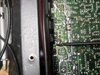
I got the radio with no finals they were in a bag so this is maybe a possibility I see the extra pad with the no banded side of the diode going to the pad that runs to the biasing vr
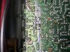
Not here to pick apart your work, just trying to help - I have a question or two...
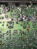
Note Circled areas, Blue ??? and Yellow Arrow...
Ok, the "bias diode" solders across BASE foil pad right next to the "amber" to ground (Banded end would be oriented towards bottom of photo)
A jumper goes from Bias "Amber" pad to BASE for BIAS - but 22 ohm resistor is on the AMBER pad side soldered across to ground on it's other lead.
So, I see ...

Coloring Legend
BLUE = BASE
CYAN = Collector
GREEN = Foil and Emitter
AMBER = BASE BIAS NETWORK
Light BLUE = AM Regulator
ORANGE = 8 VOLT TX
I just see some stuff not sure if they are "oils" from flux or are they soldering issues...?
Hope the above side to side helps you...
Where your "tip" is, is an RF bypass cap - so to see 6.9K is about normal - the thing keeps RF to where is needs to belong - and DC ground and any voltages OFF of the back panel
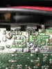
Note Circled areas, Blue ??? and Yellow Arrow...
Ok, the "bias diode" solders across BASE foil pad right next to the "amber" to ground (Banded end would be oriented towards bottom of photo)
A jumper goes from Bias "Amber" pad to BASE for BIAS - but 22 ohm resistor is on the AMBER pad side soldered across to ground on it's other lead.
So, I see ...
Coloring Legend
BLUE = BASE
CYAN = Collector
GREEN = Foil and Emitter
AMBER = BASE BIAS NETWORK
Light BLUE = AM Regulator
ORANGE = 8 VOLT TX
I just see some stuff not sure if they are "oils" from flux or are they soldering issues...?
Hope the above side to side helps you...
Where your "tip" is, is an RF bypass cap - so to see 6.9K is about normal - the thing keeps RF to where is needs to belong - and DC ground and any voltages OFF of the back panel
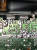
Ok, looks a bit better - but I'm still wondering the loss of voltage - and you did say the pots were ok...?
I see you have them back in..
I guess - carefully - reapply power...
I see you have them back in..
I guess - carefully - reapply power...
dxChat
- No one is chatting at the moment.