• You can now help support WorldwideDX when you shop on Amazon at no additional cost to you! Simply follow this Shop on Amazon link first and a portion of any purchase is sent to WorldwideDX to help with site costs.

Galaxy 2517 ept690010d Low power in am and fm mode

Enterprise312ok

Sr. Member
Jun 12, 2022
514
549
103
36
Well this one is my personal base station, Saturday morning I noticed It was putting out very little power in am and fm mode, ssb seems unaffected.
The middle leg of Q54 q54 only reads 1.8 volts in am and fm with both internal variables and rf power knob at max. In ssb the center leg of q54 reads 12.5 volts and is adjusts properly with vr17. I have checked q53 q56 c242 c238 c179, tomorrow I will continue to check the other components in the area as I have time.
 

Looking at the schematic, I find the only difference, between "AM or FM" and "SSB" modes, to be D96 (1N4148) and R251 (1.5K) are used in "AM or FM" mode only and not in "SSB" mode (R300 is for all three modes) ........

Check for a voltage change at:
Both sides of D96
Both sides of R251
Both sides of R300

Both sides should have a voltage change when in "AM" or "FM" modes from "SSB" mode. They are all located near VR16 and VR18.

If there is no voltage change starting at D96, then D96 is bad.
If there is a voltage change to all three then that circuit is fine.

Hope this helps some.
Good luck
 
  • Like
Reactions: Enterprise312ok
I replaced the diode even though it checked good, in ssb mode rx
Unbranded end 0 volts
banded end 0-2.5 volts varies with rf power control on face of radio

Am mode rx
unbanded end: 7.96 v
banded end: 7.33 to 7.34
rf power control does not have much effect.
 
r251 am mode, leg nearest front of radio stays at 7.33
leg closest to back of radio
4.49 with power down,
4.84 with rf power up
 
let's start from scratch.

put the radio in LSB, mic gain all the way down (off, no RF to IRF520s)
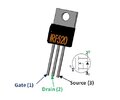
key up (TX). measure the voltage at all the IRF520 gates.

let us know. should be around 3.7 V. but anyways,
do this.....

Do the bias adjust thing. just to make sure.
remove the shorting board, adjust for
bias current at each IRF520. it's in the manual.
make sure about 20 to 50 mA each device.

then try to adjust for AM mode.

I will explain later. . gotta get another beer!!!!
 

Attachments

  • IRF520.jpg
    IRF520.jpg
    17.6 KB · Views: 2
I have already set the bias for current gate voltage is around 3.5 for driver and final, the mirror board voltage is what is killing me, The radio will swing 40 watts but I can only get about 1.5 watts carrier with the 2.8 volts to the mirror board..
In ssb mode the unit works perfect, adjusts from 3.5 to 13 volts at the mirror board.
 
Could there be a fault in the cw circuit causing the am trouble? Voltage at mirror board is even lower in cw mode. Also a previous tech or owner has removed jp4 and when I replace it the unit stays in tx mode.
 

dxChat
Help Users
  • No one is chatting at the moment.