• You can now help support WorldwideDX when you shop on Amazon at no additional cost to you! Simply follow this Shop on Amazon link first and a portion of any purchase is sent to WorldwideDX to help with site costs.

Galaxy 33hp Help identifying mod

Eldorado828

8-2-8 in the Lonestar state
Feb 21, 2016
3,839
7,219
523
The Lonestar State
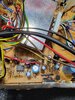
Quite some time back I picked up this radio at a local antique store for 20 bucks thinking it could be a parts radio. In the pursuit of escaping reality for a couple of hours this evening thought let's bust it open and see if it's all there before putting power to it. So all inside looks good and wasn't even converted to 11 meters yet, but.... Tr32 was missing so installed a new one. Removed the jumper to convert, plugged it in and voila it actual works.

I'll stop with the diary now and get to the meat...

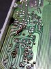
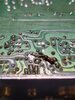
So it transmits and receives but talk back sounds like crap if one were to use it. Dk settings are about normal, pep seems ok but gets really warm fast around the audio ic and regulator. 20211229_192045.jpg Now on the foil side by tr41 is a resistor that kind of looks out of place but solder looks kind of factory. Is this a mod or is it a factory afterthought.

One end is at the + side of c143/j7/r259 junction and the other end is at + side of c199/r162/d65 cathode side junction.

Do any of you fine fellows recognize this as a mod/fix or know what it may be do there? I can't tell the colors of that resistor but could remove it and check it with the mm if needed.

Any of your input is appreciated.
 

Attachments

  • 20211229_183653.jpg
    20211229_183653.jpg
    1.4 MB · Views: 22
  • 20211229_183709.jpg
    20211229_183709.jpg
    1.3 MB · Views: 23
  • 20211229_192029.jpg
    20211229_192029.jpg
    2.1 MB · Views: 22

DX33 unknown added resistor.jpg

The center pin of TR41 is the Collector, or output of the +8v Voltage Regulator.

My best guess is they doubled the resistor R162 with another 100 ohm (making the total resistance half, or 50 ohms, 2x 100 in parallel), to double the current across R162. The Diode drop voltage across D65 is or should still be 0.7v.

This should have no effect on the bad sounding talkback.
 
View attachment 49330

The center pin of TR41 is the Collector, or output of the +8v Voltage Regulator.

My best guess is they doubled the resistor R162 with another 100 ohm (making the total resistance half, or 50 ohms, 2x 100 in parallel), to double the current across R162. The Diode drop voltage across D65 is or should still be 0.7v.

This should have no effect on the bad sounding talkback.

Thank you sir, so might this be some sort of revision they did afterward? You were able to tell the band colors better than me, they looked either white or Grey which didn't make any sense to me.

Wasn't sure if it was some hack mod that I'd never seen.

As far as talkback, there's a resistor mod to clean that up if I memorize serves me right so I'll chase that when time avails.

Hopefully tonight I'll check bias and such to see why that sucker gets hot so quick.

I appreciate the reply
 
I was going to post this last night, but fell asleep in my chair while searching my notes directory on my laptop.

Galaxy 55 Talkback.jpg

I posted this a while back. Could also put a capacitor in series, too, to change the tone.
Like on the RCI2950 pre-DX, similar setup.

RCI-2950-70 pre DX Talkback mod.jpg

It goes between Pin 1 (output) of the 4558 Mic amp chip (dual op-amp) to Pin 4 of the TA7222 or Pin 1 of the TDA2003 if that radio has the TDA instead.
 
  • Like
Reactions: Eldorado828
20211231_001926.jpg

Maybe it is a factory redesign after the silkscreening?
This is in a Connex 4300 I have in my storage, has some issues (other) that I need to get a round tuit some day.
The yellow wire goes to an empty hole where J9 in the front of the board goes, I will flip the board over and see where that trace goes to tomorrow.
 
View attachment 49352

Maybe it is a factory redesign after the silkscreening?
This is in a Connex 4300 I have in my storage, has some issues (other) that I need to get a round tuit some day.
The yellow wire goes to an empty hole where J9 in the front of the board goes, I will flip the board over and see where that trace goes to tomorrow.
Thanks for the help and info, I'm back to this radio today and see what else we find.

@Handy Andy I checked the above you mention and just as @NZ8N found in his 4300 I also found in a junker 3300 hp board that's in the parts pile. That said, it looks like that part is a later revision.

@NZ8N I think I'm going to check the resistor in the r210 location that's on the components side to see if it's OK, thinking maybe the one on the foil side was added rather than replacing the one on the components side? Maybe?

Now to the talkback, thanks again for your mention above on the talkback. That looks slightly different as this radio already has talkback. The talkback mod I recalled was this one below, I'll see how yours can apply to this one if it has better benefit. This board is the ept3600-14b with the TA7222 audio chip.

I'll update as I go through it today. I appreciate your help!

Screenshot_20220101-102459_Chrome.jpg
 
  • Like
Reactions: Handy Andy and NZ8N
DX33 Talk Back variances.jpg
They are both variations on the same theme.
My variation (red) goes direct from output pin of the MC4558 (NJM4558) to the input pin of the TA7222, capacitor optional, or could be used to change tone.
The other variation you posted (green) goes from the capacitor and resistor that feeds AM modulation audio to the Power Control circuit, the other side of R207 is directly grounded by one section of the mode switch (in FM), so may have a difference in talkback level from mode to mode. May.
Orange then C187/R207 then blue indicates this path.

Try it both ways, tell us what you find!

Edit: I had the audio amp side of the green on the wrong junction, I re-edited the pic and reposted the corrected variation.
 
Last edited:

dxChat
Help Users
  • No one is chatting at the moment.
  • dxBot:
    Tucker442 has left the room.
  • @ BJ radionut:
    LIVE 10:00 AM EST :cool:
  • @ Charles Edwards:
    I'm looking for factory settings 1 through 59 for a AT 5555 n2 or AT500 M2 I only wrote down half the values feel like a idiot I need help will be appreciated