Got this Galaxy DX-55V on the desk. This is one of two 55v's I been working on lately. The other had no driver bias, thanks to another user (Cable Guy I think) it's back to working.
However, this other one is a boo boo on my part. As usual, I yanked out the junk regulator swing mod, replaced all three limiters (yea I know it makes no sense to remove them all, lol...) and replaced R174 and R187 with 5.1k Ohms each. Those spots come factory with 10k ohm each, but some "watt meter" techs like to drop those values down as low as they can just for watt meter pride. These locations should only be changed out IF, and only IF you require a little more drive to the mic amp. To low of a value in those two spots will overdrive that mic amp and could cause issues. Why stress out a good radio for only a couple of watts difference? If I feel the radio needs more drive, then I'll swap those two resistors out with 5.1k ohm in each spot. This radio had 2.2k ohm in each spot, way too low for my liking.
Well, after I replaced those two resistors with 5.1k Ohms each, then is when the radio got stuck in transmit mode. Every time I turn the radio on, it's keyed up by itself. Even with no mic hooked up. If I hook the mic up and press the PTT, then it makes no change, still stuck in transmit mode.
After checking over my work I noticed I had shorted out the R174 (TR32 collector side) with ground. I also noticed I shorted out the R187 lead (farthest lead from chassis) to the other two closest solder joints beside it, one went to ground (emitter of most of the transistors in that section).
After completely removing those resistors and cleaning up the spot, it is still stuck in transmit.
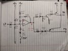
The mic amp (OP Amp) was showing odd numbers so I replaced it with a new JRC-4558D, same results and numbers.
Checked the following transistors:
TR32, in circuit it showed 8v on collector. Out of circuit it tests fine on tester and multimeter diode test.
C128, C129, tests as good caps, tolerance well within limits and ESR is good.
TR33, TR36, TR37, TR38 all test good out of circuit in tester and multimeter diode test.
C134 tests as a good cap.
Checked D77 in and out of circuit, tests as good.
Check all diodes around TR36-TR38 section, all test good.
Beginning to think C199, C131, main 8v regulator or the 7222AP IC.
Any suggestions guys/gals?
Lifted collector of Passthrough and AF regulator for safe measures to prevent blowing up the Max mod or finals. Still stuck in transmit.
However, this other one is a boo boo on my part. As usual, I yanked out the junk regulator swing mod, replaced all three limiters (yea I know it makes no sense to remove them all, lol...) and replaced R174 and R187 with 5.1k Ohms each. Those spots come factory with 10k ohm each, but some "watt meter" techs like to drop those values down as low as they can just for watt meter pride. These locations should only be changed out IF, and only IF you require a little more drive to the mic amp. To low of a value in those two spots will overdrive that mic amp and could cause issues. Why stress out a good radio for only a couple of watts difference? If I feel the radio needs more drive, then I'll swap those two resistors out with 5.1k ohm in each spot. This radio had 2.2k ohm in each spot, way too low for my liking.
Well, after I replaced those two resistors with 5.1k Ohms each, then is when the radio got stuck in transmit mode. Every time I turn the radio on, it's keyed up by itself. Even with no mic hooked up. If I hook the mic up and press the PTT, then it makes no change, still stuck in transmit mode.
After checking over my work I noticed I had shorted out the R174 (TR32 collector side) with ground. I also noticed I shorted out the R187 lead (farthest lead from chassis) to the other two closest solder joints beside it, one went to ground (emitter of most of the transistors in that section).
After completely removing those resistors and cleaning up the spot, it is still stuck in transmit.
The mic amp (OP Amp) was showing odd numbers so I replaced it with a new JRC-4558D, same results and numbers.
Checked the following transistors:
TR32, in circuit it showed 8v on collector. Out of circuit it tests fine on tester and multimeter diode test.
C128, C129, tests as good caps, tolerance well within limits and ESR is good.
TR33, TR36, TR37, TR38 all test good out of circuit in tester and multimeter diode test.
C134 tests as a good cap.
Checked D77 in and out of circuit, tests as good.
Check all diodes around TR36-TR38 section, all test good.
Beginning to think C199, C131, main 8v regulator or the 7222AP IC.
Any suggestions guys/gals?
Lifted collector of Passthrough and AF regulator for safe measures to prevent blowing up the Max mod or finals. Still stuck in transmit.