Got a doosie this time, you all are gonna love this one, lol...
First off, I must mention the inside of the speaker cover is marked SRC (Snake Radio Customs) along with a date written in magic marker ink.
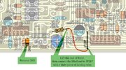
Second, the filter cap at the DC input (normally 1000uf 25v) was replaced for a 4700uf 35v. Why for a single final?
Third, someone installed a 10 turn clarifier control (hmmm...) in place of the factory clarifier control.
Fourth, and most important,
Channel 1 = 26.885
Channel 2 = 26.895
Channel 3 = 26.905
Channel 4 = 26.925
Channel 5 up to 11 is correct
Channel 12 = 27.025
Channel 13 = 27.035
Channel 14 = 27.045
Channel 15 = 27.055
Channel 16 = 27.075
Channel 17 = 27.085
Channel 18 = 27.175
Channel 19 = 27.185
Channel 20 = 27.205
Channel 21 = 27.215
Channel 22 = 27.225
Etc...
Channels 26 up to 34 go back to 27.205 up to 27.285
Channels 34 up to 40 are correct
None of the switches have any affect on the frequencies. All switches work their specified function.
It aligned great, no issues aligning it.
VCO adjusted to proper spec.
VCO Buffer aligned at max no problem.
PLL oscillators adjusted great.
Carrier oscillators aligned fine.
RF Stage adjusted fine.
Bias adjusted fine.
Receives great on all the goofed up frequencies, transmits great on all the goofed frequencies.
Transmit:
AM = deadkeys 4w, swings to 16w peak, swings up to 4.5w in average.
Sideband = 16w.
All functions work as they should with no issues.
Just the goofed up frequency pool is what's the problem.
Anyone ever ran into this?
This radio was given to me in exchange for radio work on another radio. It's my personal radio. Would like to throw this one in my truck.
Any advice on the goofed up frequencies?
First off, I must mention the inside of the speaker cover is marked SRC (Snake Radio Customs) along with a date written in magic marker ink.
Second, the filter cap at the DC input (normally 1000uf 25v) was replaced for a 4700uf 35v. Why for a single final?
Third, someone installed a 10 turn clarifier control (hmmm...) in place of the factory clarifier control.
Fourth, and most important,
Channel 1 = 26.885
Channel 2 = 26.895
Channel 3 = 26.905
Channel 4 = 26.925
Channel 5 up to 11 is correct
Channel 12 = 27.025
Channel 13 = 27.035
Channel 14 = 27.045
Channel 15 = 27.055
Channel 16 = 27.075
Channel 17 = 27.085
Channel 18 = 27.175
Channel 19 = 27.185
Channel 20 = 27.205
Channel 21 = 27.215
Channel 22 = 27.225
Etc...
Channels 26 up to 34 go back to 27.205 up to 27.285
Channels 34 up to 40 are correct
None of the switches have any affect on the frequencies. All switches work their specified function.
It aligned great, no issues aligning it.
VCO adjusted to proper spec.
VCO Buffer aligned at max no problem.
PLL oscillators adjusted great.
Carrier oscillators aligned fine.
RF Stage adjusted fine.
Bias adjusted fine.
Receives great on all the goofed up frequencies, transmits great on all the goofed frequencies.
Transmit:
AM = deadkeys 4w, swings to 16w peak, swings up to 4.5w in average.
Sideband = 16w.
All functions work as they should with no issues.
Just the goofed up frequency pool is what's the problem.
Anyone ever ran into this?
This radio was given to me in exchange for radio work on another radio. It's my personal radio. Would like to throw this one in my truck.
Any advice on the goofed up frequencies?