• You can now help support WorldwideDX when you shop on Amazon at no additional cost to you! Simply follow this Shop on Amazon link first and a portion of any purchase is sent to WorldwideDX to help with site costs.

Galaxy DX55HP low power

Buzzard78945

Active Member
Feb 8, 2020
126
31
28
33
well I think it’s broke...

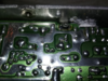
I had a problem the so-239 connector was spinning the center Terminal and intermittently getting a bad connection... I was dropping in and out receive and TX... I KNOW NOT GOOD

so I changed out connector and now it’s looking like I have an issue of low power...
The dead key don’t adjust no more I have hardly any swing just hangs out around 8 watts

funny thing is SWR is AT 2 all the time!!!! Even hooked up to dummy load... yes I checked it with a different radio dummy load shows perfect SWR

blown final??????????
 

No, wrong reconnection point...

There is an SWR "slot" on that board, but you have to follow the traces from L31 that last coil - into a junction using a spot on the board that goes to the SWR slot past 2 caps C158 and C159 - you FOLLOW the Trace to C158 - just before it goes to the SWR board "slot"

upload_2020-4-5_23-12-1.png

It needs to be pretty close to that spot...
J503 connector location.jpg

Better view?
upload_2020-4-5_23-16-36.png

Make sure you have it in the right hole and you're not soldering any parts together you shouldn't

upload_2020-4-5_23-13-47.png
 
  • Like
Reactions: tecnicoloco
Ya that top picture is what it done previously I’m thinking to cause this issue... ( for anyone else viewing this post )

I did install a new jumper wire to the exact location it was and it is the correct location denoted there

what could cause the SWR being high?
All the time?
 
I tried uploading a video but I haven’t been able to figure out how yet.. I just my cell phone for most pictures and such I don’t know how to get a video uploaded with computer either... it won’t let me


Buttttt here is a pic of where the original location was 09F62C79-1278-469F-8099-BD287E12D4F7.png
Looks correct????

I just put me a new wire back in that same position
 
Then it could mean - if you have the Dual Final - one Final is blown but that is BEHIND the SWR meter so I'd look into a little further back and reflow some solder from the Final on towards the SWR "slot"

Then make sure the Center Post of the antenna connector - is connected to the external "plug" end of that same connector. A Continuity Check

I've known of the center conductor "snapping" or breaking off inside the SO-239 requiring a complete replacement - your full rotation kinda thing.

Else look around from the foil side and look for cracked solder joints and reflow them just to be sure.

There are some "Tabs" back there that serve as support and board ground - if you really had to torque the connector to get it off - the wire can stretch and tear foil - as well as lift up components and distort the board from it's seated position - look for "cracked" portions of the board and tap around with the cover off to look for loose or open foil parts that can start working again once they make contact.

To see an SWR of 2 - AFTER the radio - and before you had this SO-239 problem - you had something else - a good SWR - It may mean you have to look at those coils and cap make sure they are intact, or just swap out known good ones just in the area to see if your effort to remove the antenna - pulled or cracked a cap substrate and it's no longer a part of the output network "tuning" for impedance matching to the SO-239 - the area I posted earlier - for if those parts are not working (or they're shorted together now) because of the stress placed on them cracked their insulator it can make the SWR goofy and what was a good tuned system - operate poorly.
 
I changed the so-239 connector last night thinking maybe it was the cause of the issue No dice

without removing from the board... is there a way to voltage check finals to tell if they are good/ bad?

I can get schematic and such I just haven’t found voltages for the finals yet
 
Then it means by the physical constraints of rigid board, you may have broken a trace or contact - just reflow solder in the solder pads and do continuity checks -one pad to other pad In the trace - all routes from the one pad in the trace route need to be checked for "tearing foil" - I did notice you have "Solder Rivet" without a tab - did you lose a connection back there a while ago? The Chassis case appears bent...was that from the issue of that connector?
 
Take A look at these pics, they are from a Galaxy 959 - it has an SWR board, but I wanted you to review the connections and soldering done - see if you can notice any changes in your board system and especially if they are deformed.

They are full size, review as you can - I hope these "pristine" photos of a Virgin Galaxy can help you locate and fix your problems.

I wanted you to especially look at those Solder "Tabs" that are lugs that are "bolted" to the rear panel. - they support the board but also give RF a way out without inducing a Ground Loop - they use Caps as "standoff DC insulators, but the allow RF to pass thru.

Why is this important? I'd like to call it "Phasing" which may not be the true answer but RF currents in a Final and Driver section work differently when they are idle versus under power and delivery of RF - the RF "velocity" thru the different media, be it Aluminum, or Copper or Silver solder and Lead paint - all are different and they can arrive to the SAME SPOT at different times - as short runs go - when other radios use a simple Foil Board ground point, Galaxy uses an Older Cybernet trick of offering "Standoffs" to allow RF paths of escape to reduce a performance hit.

So if something got torn or pulled out of shape - it affects the balance of currents back there to a point where it hurts power delivery - an Admittance issue - now if you have a bad cap - that cap can cause the SWR reflection - by affecting the NETWORK reactive elements and cause the Impedance bump to appear - so you know...

.
 

Attachments

  • FinalCloseupFlash.png
    FinalCloseupFlash.png
    6.2 MB · Views: 10
  • FlashCloseupDriverFinal.png
    FlashCloseupDriverFinal.png
    7.3 MB · Views: 8
  • FlashFoilFinalDriverCorner.png
    FlashFoilFinalDriverCorner.png
    7.5 MB · Views: 6
  • FoilBoardFinalDrivercorner.png
    FoilBoardFinalDrivercorner.png
    7.4 MB · Views: 7
  • FoilBoardFinalDriverCorner1.png
    FoilBoardFinalDriverCorner1.png
    8 MB · Views: 9
I reflowed driver and finals... a couple other things in that area along with a couple case grounds that looked funny

I got good SWR
Good 7 watt key power adjusted all the way up
Good swing 25 watts don’t know if that’s enough

but now no Adjusting dead key with power knob adjustment

I tried this... 9C496BAE-7BE1-4AD9-839E-2B7F8DD220D9.png
Adjust VR16 with power on low.. it will not move...?????? The high power adjustment will move VR 13
 
VR13 - is it still variable - your AM power Carrier adjust.

It is my fear that one of these two, VR 16 or VR13 may have cracked breaking them open and you lose your ability to trim power.
VR16VR13AMPOWER.jpg
 
VR 13 I adjusted from 0 - 10 watts (briefly) then back to 7 ( with power knob all the way up )


And I was thinking the power adjust pot on front of radio or possibly VR 16 (both are just variable resistors correct? )

just need to ground one lead and start doing continuity checks through each circuit...
Power disconnected and caps discharged
 
Look for HEADER J104 - a 4 pin header. Centerline of the board Front facing you - BEHIND the headers towards the center of the board.

Takes the 2 wires from that RF Power and Dimmer control - those two wires go to the two CENTER pins of that header - VERIFY so you can refer to the Color code later.
  • Do a continuity check from VR13 - thru the schematics' routing shown, into the RF Power side of the front panel POT and back down to VR16 thru it into ground.

IF you think the Pot may be intermittent or acting up - check the pots shafts' to see if they are able to turn freely and not "lobbing" or off center. - DURING that continuity check to linear operation of those controls.

Check to make sure the wiring is soldered and the ground to 8 volt route is continuous, if not - replace parts or find another way of making it a permanent setting so you don't have to mess with aging parts like this.

A lot of times, the AM power adjust, as well as the VR16 "low power trim" can have FIXED resistors installed once you have the power levels set - the trimmers can be removed and measured
  • - at the pins with the single side being the variable side, will be one leg of the resistor with the other side to ground being the other leg of same resistor - measure between the two points of the variable one from center to the other pin that goes to the ground foil side and choose approximate close FIXED value
  • then a fixed resistor can be installed for VR16
  • - VR13 ??? OTOH will need a DIVIDER - meaning 2 resistors will have to be used to set mid-point voltages.
    • It's REQUIRED to use two - and you run one resistor to the 8V rail to center - the other to ground from center
  • - this divider network then replaces any further problematic issues with variable power settings - just let the RF power on the front panel do the rest of the work for you.
I had to do this on another older AM regulator style radio that it's owner kept using the AM Power pot to run various amps - so he eventually broke the trimmers and finally he asked for the "SET and Forget" method and so the Divider Network was used to repair and take over his desire to power amps with different settings and we simply let him run with an NPC mod instead to handle his swing level desires instead.
  • There's a lot to be said about the NPC mod and people don't always know that the NPC effects can be controlled to a degree thru the use of a simpler 1K or even 5K variable - but you didn't hear that from me...
 

Attachments

  • 1aAsymmetryVariantsNPCCombo.jpg
    1aAsymmetryVariantsNPCCombo.jpg
    380.1 KB · Views: 9
Last edited:
Ok I only had 10 min to play with the 55 tonight I peaked my 33Hml (no couldnt tune I don’t have a freq. counter or scope.... I know I know)

anyways so I did some power off continuity checks I hooked up leads to pot VR16 it’s wonky... it’s a “1K” pot ( what’s shown on it ) and it was 1200ohm all the way one way then you start moving it slowly monitoring resistance and it goes 1200...1100...800...500.... and then a little under 500 it goes to 0 ohm and stays I think it’s bad I was gonna hook up to ground end of pot and check it that way to but the case i only showing open (millions of ohms) hummmm I’m still confused by all radios and their ground... case ground isn’t always ground figured that out the hard way.... where do I hook a ground to?

Anyways that pot shouldn’t be reading 1200 in the first place much less skipping around then going to dead short half the pot so ima try changing it... ima have to order one or borrow one from my 33HML
 

dxChat
Help Users
  • No one is chatting at the moment.