I just built a 2 tube GS35B amplifier. My question is when I activate amp with foot pedal, I have a grid current of 400ma with no drive on the input. Does anyone know if this is normal? The amp is biased at 30V. I was told by someone that there should be no grid current until I apply some drive. Is this correct? If so, should I start looking at bias section and see if something is amiss? Any help on this I would appreciate, first time building a tube amp. Still have lots to learn.

You are using an out of date browser. It may not display this or other websites correctly.
You should upgrade or use an alternative browser.
You should upgrade or use an alternative browser.
-
You can now help support WorldwideDX when you shop on Amazon at no additional cost to you! Simply follow this Shop on Amazon link first and a portion of any purchase is sent to WorldwideDX to help with site costs.
-
A Winner has been chosen for the 2026 July 4th Retevis RA89R Giveaway! Click Here to see who won!
Grid Current?
- Thread starter Crusher
- Start date
I installed the plate current in series on the B- side and then the grid current meter afterwards and one side of the grid current goes to ground. I used a 50 ohm 45 watt resistor to float my B- above gound. You may be right, because I am not seeing any plate current.
I installed the plate current in series on the B- side and then the grid current meter afterwards and one side of the grid current goes to ground. I used a 50 ohm 45 watt resistor to float my B- above gound. You may be right, because I am not seeing any plate current.
Crusher, I did the same thing with my GS35B amp, my B- was 50 ohms above ground, that was too much. I dropped the 50 ohms down to 1 ohm.
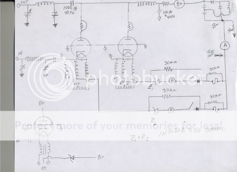
This is what it looks like on paper however, where the diagram shows Zener #1 and Zener #2, I have installed separate Triode control boards which allows me to individually set the idle current for each tube.
The meter that you have to measure Grid Current could be throwing you off (I had to remove mine from that position because my current wanted to through it instead of to my B-). I think that your meter and the "Float" resistance above ground represent a lower resistance path than does your B- connection.
Try this and see how it works, temporarily remove the Grid meter from the circuit, lower the 50 ohm to something a lot lower, like 2 ohms and calculate your Grid current from the voltage drop to ground across that resistor (Current equals voltage divided by resistance).
At idle, with 3000 volts, my plate current is adjusted to 150 mills per tube and each tube runs about 20 mills of grid current; with 50 watts drive I am seeing about 1200 mills of plate current and 200 milliamps of grid current.
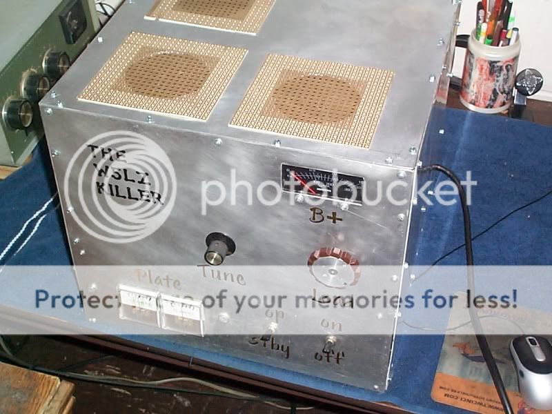
Do you have any pictures of your amp?
.
I have pictures, will upload them in the next day or so. I used a 5 amp meter for plate current and a 2 amp meter for grid. I found them on ebay and didn't have to use seperate circuit, shunt built into meter. I have a couple of 5 ohm 50 watt resistors I will put in series and try it. That should give me 2.5 ohms at 100 watts. Overkill yes, but I have them on hand. I used a zener diode to drive a pass transistor. 2n5686. The bias circuit is bypassed with many 103's to keep rf out of circuit. I will get pics up as fast as I can, hard drive crashed and waiting for new one to arrive. Then I should be able to recover files. All I have at present is my phone.
Paws, just out of curiousity what did you drive your amp with? I know that all is needed is about 100 watts pep per tube. But I ain't worried about max at this point. I used a PD 2800V @ 1.5 A CCS transormer for plate. Probably should have gone slightly bigger, then as I said, not looking to squeeze every watt out of tubes. And yes I install 2 27 ohms resistors in parallel. For glitch resistor. They are rated at 20 watts each. Also installed 4 inch piece of #30 gauge enameled wire on 4 inch ceramic standoffs. For HV fuse. Soft start. Installed a HV meter and a few other features. One thing I would like to install yet but not sure how to yet is install circuit so that if there is a problem with HV circuit, like a short or something. Trying to figure out circuit so that if there is a problem it will keep circuit at lower voltage instead of full power. Some kind of sense circuit. I used 15kv vacuum variable caps for both plate and load. I have a high impedance choke I installed on tank circuit if blocking caps would short. I used 2 680pf @ 20kv in parallel for blocking caps. Amp was built for mono band use. Used PI circuit for input and output. Only thing that might be an issue is I used a single bias circuit to operate both tubes. I was able to use 2 of the radio shack 12.6 volt @ 3 amps for filament.
Sorry it took so long to get back....I have been fighting the "Slings and Arrows of outrageous fortunes".
Paws, just out of curiousity what did you drive your amp with? I know that all is needed is about 100 watts pep per tube. But I ain't worried about max at this point.
I am driving it with a Yaesu FT-101 which is lucky to get 100 watts total (I am running about 50 watts DK). My grid current is around 150 mills per tube (low) and, I am running 1200 mills Plate current out of 2 tubes.
I used a PD 2800V @ 1.5 A CCS transormer for plate. Probably should have gone slightly bigger, then as I said, not looking to squeeze every watt out of tubes.
My bench supply is not up to the job (2 JB-2000 transformers wired either in parallel for 2500 volts at 1 amp or in series for 5,000 volts @ 500 mills). Working on getting my larger supply done, I just need a safety enclosure.
And yes I install 2 27 ohms resistors in parallel. For glitch resistor. They are rated at 20 watts each. Also installed 4 inch piece of #30 gauge enameled wire on 4 inch ceramic standoffs. For HV fuse.
My glitch resistor is in my bench supply; I was strongly advised against using the piece of wire as a HV fuse, I was told that the high current conditions could substain an arc via the vaporized pieces of the wire.
Soft start.
Did not see a need for a soft start with the tubes but, I bring the HV up with a variac after a warm up period for the tube.
Installed a HV meter and a few other features. One thing I would like to install yet but not sure how to yet is install circuit so that if there is a problem with HV circuit, like a short or something. Trying to figure out circuit so that if there is a problem it will keep circuit at lower voltage instead of full power. Some kind of sense circuit.
I install a B+ meter in everything I build. The Triode control board is my main saftey circuit, I could wire it so that if it reaches a certain current level, the keying circuit would open.
I used 15kv vacuum variable caps for both plate and load.
My Plate Tune variable is 3-50 pf @ 25KV while, my Antenna Load is 20-1000 pf @ 10 KV.
I have a high impedance choke I installed on tank circuit if blocking caps would short. I used 2 680pf @ 20kv in parallel for blocking caps. Amp was built for mono band use. Used PI circuit for input and output.
I used an "L" network for the input and a standard Pi-network for the output.
Only thing that might be an issue is I used a single bias circuit to operate both tubes.
I have separate Filament supplies, Triode boards and, plate current meters for each tube; each tube is protected from over current by a fuse in the B- line. I have a meter to monitor the total current in the B- line. My B- is 1 ohm above ground, the voltage drop across the resistor to ground tell me my total grid current (cannot monitor grid current on each tube individually). You need separate bias controls on large tubes as these because of the potential difference in gain of the tubes (ask me, I know; had me going in circles till I balanced the currents).
I was able to use 2 of the radio shack 12.6 volt @ 3 amps for filament.
I doubled up and used 2 of the Radio Shack transformers per tube (total of four), my filament volts are running at 12.9 volts about 2% high, when I ran off of just one, the filament voltage sagged below a point that I was happy with.
.
50 Watts Deadkey out of a 101???
PR
So, I'm not the only one that caught that.
 x 2
x 2Those 6JS6's are not going to like that for long.
50 Watts Deadkey out of a 101???
PR
Test purposes only, quick keys!
.
ETA: If I really need to drive it, look on the left hand side of the picture.
.
.
Last edited:
So, I'm not the only one that caught that.
Those 6JS6's are not going to like that for long.
I've had the same pair in there since 1985, it's time for a alignment and maybe even a new pair.
.
dxChat
- No one is chatting at the moment.