• You can now help support WorldwideDX when you shop on Amazon at no additional cost to you! Simply follow this Shop on Amazon link first and a portion of any purchase is sent to WorldwideDX to help with site costs.

Homebrew 1.2 Ghz 10 element yagi antenna

23cm spacing

Can you clarify the spacing on the 1.2 gig elements-
Not sure why but it seems confusing to me-

you start with the reflector and then space each element forward by the distance in the chart?
Joe N2GBT
 
the measurements are all from the back end of the boom.

The front element, D7, is 23 inches from the back end. D1 is 4 inches from the back end, etc.
 
2cm antenna

thanks- figured it was that simple. Just finished making the antenna- all the elements are within .01mm accuracy- for the driven element-
what is the total length of the driven element-
I see 1.75 + .5 + 1.75 on one set of plans but it appears that the driven element is one continous piece of copper- with one end epoxied in place( I will probably drill a hole and slide this end into the pvc boom)
and wrapped around the boom with 1/2 ich spacing
do you know the total length of copper wire needed/
Thanks
Joe
( just put the 1.2g module in my ts790 cant wait to try this)
 
2cm antenna

thanks- figured it was that simple. Just finished making the antenna- all the elements are within .01mm accuracy- for the driven element-

I am showing a distance fromt he reflector to the last element (D8) of 23 inches I HOPE this is correct

what is the total length of the driven element-
I see 1.75 + .5 + 1.75 on one set of plans but it appears that the driven element is one continous piece of copper- with one end epoxied in place( I will probably drill a hole and slide this end into the pvc boom)
and wrapped around the boom with 1/2 ich spacing
do you know the total length of copper wire needed/
Thanks
Joe
( just put the 1.2g module in my ts790 cant wait to try this)
 
10 el yagi specs- corrrect?

1296 MHz. This antenna is the veteran of several "Grid Peditions" but I have yet to actually measure the gain. Dimensions must be followed with great care. The driven element is small enough to allow 0.141 semi-rigid coax to be used instead of RG-58. Silicon Bronze welding rod was used for the elements but any material can be used. Driven element dimensions are L = 4.0" and H = 1/2" Elements are 1/8" diameter.
1296 MHz Reflector Driven Dir 1 Dir 2 Dir 3 Dir 4 Dir 5 Dir 6 Dir 7 Dir 8
10 Element Length 4.30 3.90 3.80 3.75 3.75 3.65 3.60 3.60 3.50
10 Element Spacing 0.00 1.70 2.80 4.00 6.40 8.70 12.20 15.60 19.30 23.00
 
The driven element's wire length is 4.79 inches. It is then important to make the overall end-to-end length 4 inches.

You can probably start with a wire length of 4.75 inches as the wire may streach a bit when you bend it around a form.
 
The measurements for the positions are not from the end of the boom....they're the distance from the reflector. Look at the 900Mhz antenna specs just above the 1.2Ghz specs on the sheet and you'll see that the reflector is at 0". On the 1.2Ghz table, the spacing of the columns is off because D8 has no value.

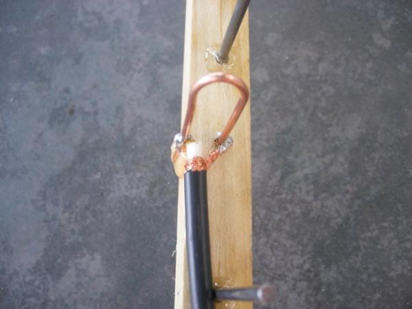
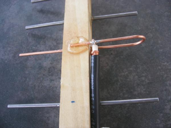
Regarding the overall (folded) wire length of the DE, I don't think it matters that much; you just want the finished width to be exact. Since the author says that you can use any diameter of wood, the placement of where the coax is soldered could also change. If the overall length mattered much, then the coax placement would be critical, too. I looked at several other variations of this using the complete folded dipole approach also. Ideally you would have an SWR meter to check it and trim the other end anyway.
 
Connection

I have been trying to understand why the wire is solder they way I see you have it in the pic, it looks like the connection will make a short circuit. am trying to build this antenna so i can use with my fpv receiver can you help me plz.
i have build a dipole antenna before , and read that the yagi has about the same principles plus the eliments.
 
I have been seeing this driven element design more often , on commercial installs ,
like at a truck stop on I-5 in northern California...
for this small size antenna Im wondering if a plan could be worked out to
just hammer in nails at about the right spots and get something with about the same results?
also anything but a top notch 'N' connector seems to kill 1296mhz signals,
I was lucky to find a very used heathkit wattmeter to help weed out the bad connections.
http://hem.bredband.net/heathkit/Products/pageIM4190.htm

Cu on ao92 L mode ko6kL
http://www.valleymedia.org/satchat


>>>The driven element is 12ga house copper ground wire. (WA5VJB used 10ga wire,

657-1251666081-e6adbd51ce6e4d61e5c8bde4edcb06ff.jpg


658-1251666081-5f18587a13a4d90492022a1421d986c4.jpg
 

dxChat
Help Users
  • No one is chatting at the moment.
  • dxBot:
    Tucker442 has left the room.
  • @ BJ radionut:
    LIVE 10:00 AM EST :cool:
  • @ Charles Edwards:
    I'm looking for factory settings 1 through 59 for a AT 5555 n2 or AT500 M2 I only wrote down half the values feel like a idiot I need help will be appreciated