• You can now help support WorldwideDX when you shop on Amazon at no additional cost to you! Simply follow this Shop on Amazon link first and a portion of any purchase is sent to WorldwideDX to help with site costs.
  • A Winner has been selected for the 2025 Radioddity Cyber Monday giveaway! Click Here to see who won!

HR2510 Front end overload.

Low_Boy

Sr. Member
Jan 21, 2010
1,934
1,202
173
Rochester N.Y.
I am working on a HR2510. Thought I had all the bugs worked out except the front is overloaded on receive. If I turn the RF gain almost all the way back I can start to hear people about 6 miles away. I tested.
D1
D2
D17
D18
Q101, Q104, Q102 ,Q118
All good. Not what sure to do next. Ideas please.
 

Use this as a guide...

upload_2020-3-5_17-7-5.png

AGC is done way back at IC101...

By your symptoms your AGC line appears to be "Dead" so that can mean a blown diode (D146 - 3.83V ZENER) or bad caps and or D117/D118 mess back at Pin 1,2 and 3 of IC101 - which it's output Drives METER - so if you see goofy (READ:TOO LOW) results on your S/RF meter - it's with D117/D118 multiplier mess or in that area (By L105 - BEHIND FM BOARD TOWARDS THE FRONT), else the AM and SSB AGC caps C41 and C42 and C7 need to be checked C41/C42 are by IC101 section C7 is further towards the rear of the board....also check your MC301 PIN diode section too D101 and D102
 
Last edited:
I will keep you posted. Thanks Usually this problem has been easy. Always ends up being a diode. Not this time though.


A good way to look at this is...

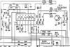
Thru your S/RF meter - if it's nearly full scale and you have to turn it WAY DOWN to obtain a "natural" reading you've gotten before on the other 2510's you've worked on, then you know the problem is with the AGC portion of this AGC detector / Amp driver circuit.

Q118 simply lets Pin 14 send it's power into that 8.2K and 3.83V ZENER.

IF you don't have any voltage on that line - your AGC Pin 12 INPUT or Pin 3 of S/RF meter needs to be checked (refer to the TOO LOW reading versus TOO HIGH to be "natural").

TOO LOW means that the "detector" portion of the circuit is not sending power to Pin 3 thru those two diodes D117 or D118 (Multiplier design). It has nothing to turn AGC on with so you get full amplification.

IF that ZENER Blew - you'd have VERY HIGH S/RF meter action but would have some useabiltiy because the 8.2K resistor is allowing current to push down the PIN DIODE "window" thru C7. D178 is sending power of the IF stage amp Q104 - so there is some AGC happening there...Q104 is attenuated thru the difference in voltage drop across it's emitter resistor R23 a 680 ohm resistor - There is a cap C18 on the Emitter line - that if it is shorted - you can have all kinds of AGC happening and things look normal - but C18 isn't letting the Emitter even see that resistor - it's fully on.
upload_2020-3-5_21-3-11.png
If C7 shorted out, you'd have full scale no variability of meter all noise hiss stuff - shorted out cap drains the line of all control including the IF amp D178 Q104. Q118 can fail if left in this state though - D146 also will fail until shorted or blows open. Either case the circuit from C7 back to Q118 needs to be checked. You can use a 1K resistor across the 8.2K to see if S/RF meter Falls to check the status of the AGC line - if the Meter falls, then the issue is with that part of line - not the IF side.

upload_2020-3-5_21-9-24.png
The 1K across R2 trick only affects the PIN diodes
The IF AMP Q104 would not be affected...​

MC301 PIN don't always go but they can blow open - then AGC works back at D178 and C7 just stays charged a real long time until it can drain back thru D146 into D178 mess at Q104. Again, the METER looks goofy because of this kind of response. It LAGS - because C7 is draining as D146 equalizes and R2 works against the input flow of current into the C7 cap. It holds this line high for a longer period of time - crashing into the noise floor until the cap loses enough charge into D178 and the Q104 IF amp opens again rushing noise into the receive.

It is my guess that the Pin 12 feedback loop from Pin 14 back to Pin 12 and Sense from Meter to Pin 12 is your main route to look into - that area takes two sections and METER action shows one way, while AGC action but no attenuation - means the Caps in the AGC Sense section, or beyond into Q118 is bad.

Clear as Mississippi Mud - right?
 
Last edited:
  • Like
Reactions: WECSOG
I'll go back over my notes. Is there any way to get the audio output into even a 500kz old skooll 'scope?
 
Old school?

Let's go...

You want the AF out at Detector or something else more exotic?

Try TP1 - but that is for SSB - might not work on a 500kHz but ... 10.695MHz stuff...

Which reminds me...

@Low_Boy - how is the SSB receive, the same thing? Or only AM?
 
@Low_Boy - Good luck.

Your RF Gain still works, but to help, it is easier to remove the two caps,
  • - one is C7, from the AGC to the Diodes D102 and D101
  • - and the C18 cap
Now - the RF Gain will still work, but if you find that your radio seems to have now a workable albeit somewhat distorted audio receive and RF METER seems to work ok, the caps simply "cushion" the lines otherwise "jittery" - clamp type of response to audio - making it sound monotone-ish.

IF that is the result, just replace the two caps...it's one of the quicker fixes I've done for this condition - usually it's one but replacing both is a simple cheap effective option due to age...

Because the other more expensive options are replacing the Quad Op Amp Chip IC101 that NJM 2902- if this is left to itself - it can damage the chip along with all those other parts...
 
Heres' some other stuff...

TP1 location - for @kopcicle ....
upload_2020-3-6_17-56-9.png

For you @Low_Boy ...

D117/D118 - that gold star item on previous post...
upload_2020-3-6_18-52-32.png

Just some fun stuff - C24 shunts the signal to help the AM/FM metering is balanced to SSB and CW side...
 

Attachments

  • upload_2020-3-6_18-52-9.png
    upload_2020-3-6_18-52-9.png
    86.2 KB · Views: 11

dxChat
Help Users
  • No one is chatting at the moment.