I recently used this radio..receiving op said youre 59 but your audio is watery..so stupid me said seems like the old TS440 pll lock problem..so I adjusted the vco coil L14 and now radio doesnt change frecuencies and voltage at TP3 is 7.35, doesnt change if I adjust L14 vco coil..what Im I looking at and what to do next? I have the service manual and the first PLL alignment procedure is a fail since I see no voltage change at TP3..

You are using an out of date browser. It may not display this or other websites correctly.
You should upgrade or use an alternative browser.
You should upgrade or use an alternative browser.
-
You can now help support WorldwideDX when you shop on Amazon at no additional cost to you! Simply follow this Shop on Amazon link first and a portion of any purchase is sent to WorldwideDX to help with site costs.
-
A Winner has been selected for the 2025 Radioddity Cyber Monday giveaway! Click Here to see who won!
HTX-10 pll problem?
- Thread starter codecxbox
- Start date
I would blame the 'watery' sound on a bad electrolytic cap. But now that slugs have been turned it seems there is more than one fault.
Do you have an oscilloscope? Never have learned how to troubleshoot a PLL circuit with just a meter. Always had 'scopes on hand, and that's the only way I know.
The only schematic I have for that model is impossibly grubby and not readable. Not sure what to recommend beyond that.
73
Do you have an oscilloscope? Never have learned how to troubleshoot a PLL circuit with just a meter. Always had 'scopes on hand, and that's the only way I know.
The only schematic I have for that model is impossibly grubby and not readable. Not sure what to recommend beyond that.
73

Are you sure you have the right guy? My YT presence is vanishingly small and always years out of date.following you on YT quite long..
The Magnum schemo is actually readable. The only actual PLL adjustment is L14, the VCO coil. All the other alignment steps shown are to trim a crystal onto frequency.
Turning L14 should not have put it to sleep unless the tuning slug has cracked and a fragment fallen off. It's my habit to watch the VCO tuning voltage with a 'scope. If there is any funny business going on, it tends to show up on the tuning voltage as noise or ripple of some sort. Can't see that with just a meter.
73
the L14 slug is fine..I can turn it from top to bottom easy..I hear mostly 11m stations but turning to almost the top, I can hear CW and Brazilians AM ops at AM at 28.310Are you sure you have the right guy? My YT presence is vanishingly small and always years out of date.
The Magnum schemo is actually readable. The only actual PLL adjustment is L14, the VCO coil. All the other alignment steps shown are to trim a crystal onto frequency.
Turning L14 should not have put it to sleep unless the tuning slug has cracked and a fragment fallen off. It's my habit to watch the VCO tuning voltage with a 'scope. If there is any funny business going on, it tends to show up on the tuning voltage as noise or ripple of some sort. Can't see that with just a meter.
73
Nope, just Nomad Radio.Are you Radionut on YT?
The 7.35 Volt reading for the tuning voltage tells you that the PLL is not locking onto the desired frequency at all. If the PLL was locked, turning the slug in L14 would change the tuning voltage, but not the frequency the radio hears or transmits. When you turn it, the receiving frequency changes, but the tuning voltage doesn't.
When a PLL won't lock, it usually means that one of the inputs to the PLL is missing. The PLL in this radio is one internal section of a chip with 80 pins on the front panel/display pc board. First thing I would do is to probe an o'scope to pin 1 on the monster PLL/display chip and check to see that a healthy 4.5 MHz is feeding into it. Pin 75 should have your local-oscillator, the PLL's VCO. Pretty sure this radio uses the high side, 10.695 MHz above the channel frequency. That chip is pretty reliable, and you'll play the devil replacing it if it's really bad. My bets are on one of those two frequencies missing in action, not feeding the chip.
73

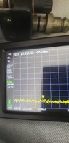
btw, I will have a proper osc by 2 weeks I hope..so far using a TinySa I probed again the CPU pin 1, I see 4.5 MhZ at 2.30 Volts. the HTX10 service manuals indicates that voltage is correct. And Im not getting any signal from the 10.695 crystal..So how about D30 the VCO coil's varactor? what voltage should I excpect?Nope, just Nomad Radio.
The 7.35 Volt reading for the tuning voltage tells you that the PLL is not locking onto the desired frequency at all. If the PLL was locked, turning the slug in L14 would change the tuning voltage, but not the frequency the radio hears or transmits. When you turn it, the receiving frequency changes, but the tuning voltage doesn't.
When a PLL won't lock, it usually means that one of the inputs to the PLL is missing. The PLL in this radio is one internal section of a chip with 80 pins on the front panel/display pc board. First thing I would do is to probe an o'scope to pin 1 on the monster PLL/display chip and check to see that a healthy 4.5 MHz is feeding into it. Pin 75 should have your local-oscillator, the PLL's VCO. Pretty sure this radio uses the high side, 10.695 MHz above the channel frequency. That chip is pretty reliable, and you'll play the devil replacing it if it's really bad. My bets are on one of those two frequencies missing in action, not feeding the chip.
73
On my Magnum 257 schematic it shows D25 as the VCO varactor, connected to L14. I would put a 'scope probe on TP3 to watch the VCO tuning voltage for a response to turning L14. Touching a probe tip directly to a varactor will change the circuit's capacitance. A 'scope probe's tip always has capacitance to ground. Usually enough to disrupt the circuit. An unshielded meter probe wire will nearly always disrupt a VCO circuit if it touches the varactor. A voltmeter is not a good tool for this. It's fine for setting L14 to the recommended TP3 tuning voltage in a working unit. Not so useful for troubleshooting. If any funny business appears on that tuning voltage at TP3, a 'scope will show it to you. A meter won't.
I never learned how to troubleshoot a PLL with a meter alone. Always had a 'scope at hand for that task.
The 10.695 crystal does not run in AM receive mode. It runs in AM transmit and for sideband receive and transmit both. Key the mike and see what it reads.
73
I never learned how to troubleshoot a PLL with a meter alone. Always had a 'scope at hand for that task.
The 10.695 crystal does not run in AM receive mode. It runs in AM transmit and for sideband receive and transmit both. Key the mike and see what it reads.
73
Last edited: