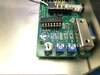
Also the board is mfg for both TO-92 and SOT-23 packages. You can do your measurements on the empty holes (TO-92) so you don't short anything.
The above voltages were taken with a 9v battery and the unit turned on but not hooked to anything.
-75
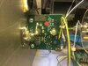
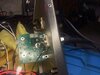
added... ok, here is a MFJ-868B I opened up for above measurements. AGAIN..the green orange and brown wires for forward/reverse going to the rear board where the SO-239's are mounted were Not soldered in. Just pushed through the holes and bent over some. I tacked them in and then snipped off the excess. Quality Control done by JB/17. Also, look at the RED wire used as a ground instead of a black wire. Very professional for a commercial item. So I thought I would check the calibration of the meter as compared to one of my Bird 43's and my Peak Reading meter. On the 20W scale the pot would not adjust high enough to read the proper wattage. As found (with the pot cranked to max was 40% out of tolerance. That's huge!! 200W and 2KW scale were out 18% but were adjustable to reflect the correct readings.


Last edited:

")