• You can now help support WorldwideDX when you shop on Amazon at no additional cost to you! Simply follow this Shop on Amazon link first and a portion of any purchase is sent to WorldwideDX to help with site costs.

ideas for a DIY signal generator for radio alignments?

brandon7861

Loose Wire
Nov 28, 2018
1,107
1,200
193
I am working my way towards being able to do radio alignments, learning along the way. Last night I learned just how touchy the adjustment is in my frequency counter as I spent 3 hours aligning it to WWV. The week before I made a high impedance active probe recalling how my galaxy hated that 10x probe. With my oscilloscope capable of various measurements like SINAD and owning a decent spectrum analyzer, I am almost there. The one thing I still need is a signal generator. I have a cheap signal generator from ebay that goes up to 60MHz, but it does not have modulation and it's signal cannot go low enough for what I need without 100dB worth of attenuators hanging off it.

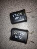
I do not need to build anything extravagant, in fact, if it is centered on 27.205MHz with the ability to shift up and down 1kHz and modulate for AM work, I would be happy. I do not need it to function at 10MHz, 200MHz or anything else. The part that worries me is getting down to -130dBm as I assume that will take a lot of shielding and various stages of attenuation.

My original thought was a common base colpitts oscillator followed by a buffer amp with the modulation signal fed into the emitter of the buffer stage and maybe a low pass filter at the output. The only good transistors I have are some 3904's, BF998's and KSP10's from mouser, the rest of what I have are fakes from amazon and parts salvaged from old radios. Any suggestions or advice (other than "just buy one") would be appreciated!

Thanks!
 

Got an older HR2510? Older Cobra 29/25?

HR2510 - Just disconnect the Final and Driver - and keep the Pre-Driver in Place...- you can make a simple "signal beacon" since the HR2510 uses LOW-Drive (meaning Audio Modulation starts at the Mixer and only goes up from there) low-level modulation. For TX (carrier + Audio) You just solder a jumper wire from the Pre-Driver Q124 amp - the output leg of C127 (the HOLE of the one lead that heads towards the DRIVER) to the output leg of the Final at the Tank Coil Circuit in this case the MRF477 is BEC - so you'd have to solder to the OUTPUT or Collector side of the part - just unsolder all legs of Driver and Final to protect them.

And at TP1 you'd have 10;69MHz and at TP304 you'd have 38MHz for anything you wish (IF Imaging)
  • So, sending carrier wouldn't be a problem, nor would it be any serious problem of any sort, as your selection of tone can be a simple squeal from feedback to help with audio peaking (SINAD - stuff)
Cobra 25/29 series can be used to help with goofy IF signal tracing - BUT they are not able to send signal because of the High-level Modulation section you're bypassing.

Cobra 29
  • Remove JP36 - solder jumper wire from Output leg lead of R58 to center Foil pad of Final Collector - again, unsolder all legs of Driver and Final to protect them - this is for TX (10.240 + 16~17MHz IF - NO OFFSET)
  • - for the output mixer of the 29 is at the connection between C85/R62 and R61 for TX, sometimes it's labeled TP4.
  • But RX has IF and is off by 455kHz - that is at C16 and R17 - that tie is TP5 on some radios and it's labeled. (TP5) (others it's TP3) - this is for those that need IF signal OFFSET of 455kHz
Cobra 25
  • The RX of the 25 is like that of the 29 (as usual) (the 10.240 and 16~17MHz IF conversion Down-Mix) so look for TP3 silkscreened on the board or the junction bare lead of R6 and C10 - again off by 455kHz
  • Output Mixer of the 25 uses TX, it's at TP4 and is the junction tie of R46/R47 and C53.
  • You might want to remove the JV17 jumper (the one that goes to the Driver and Final Collectors' from the Audio transformer)
  • But to use a buffered TX output (50Ω ohm stuff) Locate R43 10Ω resistor - lift its output leg and solder jumper wire to output tank circuit at Finals Collector (center solder pad) again, unsolder all the legs of Driver and Final to protect them.
The process above simply places the radio in a low-power mW mode for TX straight for other radio RX to "hear". The power is in Milli-watts (1/100th - of a watt) - but is useful for measuring and alignments as needed.

Especially when you DO NOT know of the IF condition of a radio
  • - so the IF signal from a WORKING radio also has an offset - you can use TP3.
  • - is it possible if you try and probe and you get a signal?
    • - tells you that you may have a radio that has IF or main Xtal working because the IF signal image to make 455kHz is used from the radios own Xtal. (Depends on where you get your IF from, usually TP3 is the 455kHz OFFSET)
    • - while TP4 has to be in TX Mode to get it.
  • Can be a great diagnostic tool to help you realign another radio if the IF of the radio under test needs to be checked or verified.
So, in a way, you can kill (er - FIX) one radio - but you still need two to tango.
 
Last edited:
Got an older HR2510? Older Cobra 29/25?

HR2510 - Just disconnect the Final and Driver - and keep the Pre-Driver in Place...- you can make a simple "signal beacon" since the HR2510 uses LOW-Drive (meaning Audio Modulation starts at the Mixer and only goes up from there) low-level modulation. For TX (carrier + Audio) You just solder a jumper wire from the Pre-Driver Q124 amp - the output leg of C127 (the HOLE of the one lead that heads towards the DRIVER) to the output leg of the Final at the Tank Coil Circuit in this case the MRF477 is BEC - so you'd have to solder to the OUTPUT or Collector side of the part - just unsolder all legs of Driver and Final to protect them.

And at TP1 you'd have 10;69MHz and at TP304 you'd have 38MHz for anything you wish (IF Imaging)
  • So, sending carrier wouldn't be a problem, nor would it be any serious problem of any sort, as your selection of tone can be a simple squeal from feedback to help with audio peaking (SINAD - stuff)
Cobra 25/29 series can be used to help with goofy IF signal tracing - BUT they are not able to send signal because of the High-level Modulation section you're bypassing.

Cobra 29
  • Remove JP36 - solder jumper wire from Output leg lead of R58 to center Foil pad of Final Collector - again, unsolder all legs of Driver and Final to protect them - this is for TX (10.240 + 16~17MHz IF - NO OFFSET)
  • - for the output mixer of the 29 is at the connection between C85/R62 and R61 for TX, sometimes it's labeled TP4.
  • But RX has IF and is off by 455kHz - that is at C16 and R17 - that tie is TP5 on some radios and it's labeled. (TP5) (others it's TP3) - this is for those that need IF signal OFFSET of 455kHz
Cobra 25
  • The RX of the 25 is like that of the 29 (as usual) (the 10.240 and 16~17MHz IF conversion Down-Mix) so look for TP3 silkscreened on the board or the junction bare lead of R6 and C10 - again off by 455kHz
  • Output Mixer of the 25 uses TX, it's at TP4 and is the junction tie of R46/R47 and C53.
  • But to use a buffered TX output (50Ω ohm stuff) Locate R43 10Ω resistor - lift its output leg and solder jumper wire to output tank circuit at Finals Collector (center solder pad) again, unsolder all the legs of Driver and Final to protect them.
The process above simple places the radio in a low-power mW mode - but is useful for measuring and alignments as needed. Especially when you DO NOT know of the IF condition of a radio - so the IF signal from a WORKING radio also has an offset - so if you try and probe and you get a signal - tells you that you may have a radio that has IF or main Xtal working because the IF signal image to make 455kHz is used from the radios own Xtal.(depends on where you get you IF from TP3 is the OFFSET - while TP4 has to be in TX Mode to get it

So, in a way, you can kill (er - FIX) one radio - but you still need two to tango.

Thanks for the info!!

I was considering that route a few months back, but the only extra radios I have laying around that haven't been robbed of parts are a midland 13-892, a uniden washington (which I would really hate to destroy either of these for this) and an old Mectron MCB-22. I don't have the schematic for the mectron, but I think it is also a high-level modulation radio.

But even if I get it down in the mW realm, I am still over 100dB too high to directly feed it into another radio, right? I might have to put the SG radio out in the shed lol. My goal is to have something I can directly connect to the antenna jack of the radio being serviced, which means even at a mW of power, I need serious attenuation and shielding, unless I am missing something ( I have never did a receiver alignment before, I just know the sensitivity I am dealing with is around -110dBm to -120dBm. Can I do a receiver alignment without getting that low by watching the audio output level?

I do have an old 9v walkie talkie that died years ago, maybe the crystal is still good. It's for ch14 though.
 
  • Like
Reactions: Handy Andy
I had an idea several years ago that I never followed through on. Take an existing radio and "butcher it" to remove the RF power stuff ...much like what Andy said.

Just a week or two ago I lucked my way into a B&K 2040 CB signal generator.
Thinking about this thing in retrospect..... that is almost exactly what it is!!!!!
A PLL synthesizer with an serious attenuator hanging off of it.

The thing the CB would lack is a crystal oven to help with stability. but with a frequency counter and "align quick"... you might do ok.
 
  • Like
Reactions: brandon7861
I suppose even if I built something, I would still have mW's of power to lower. Forgive me, when I start thinking about signals too small for my digital scope to see, I don't think clearly.

I measured the isolation in my coax switch with the connected port into a dummy load and taking the reading from the shorted port. I had 60dB attenuation there. I suppose two of those would get me close enough with a mW source that I could vary a bit, assuming the the leakage through the coax connecting them didn't find its way into the radio under test via another path...
 
Hmmm...

Interestingly enough, much of what we use today is based upon the notion that 10-11MHz signals are "no-mans Land" (WWV) region where no one maker can use that spectrum, so it's been reserved for other use - being that 10MHz IF being the most predominate signal out there - 10.240 is another spot of use in that tiny bit of spectrum.

When you realize how strong that 10.240 signal is inside a radio - I can understand your desire to feel "I don't want it" because of what damage it can do.

But you would need something there to inject - for if you did work on CB radios the 10.240 is really for the 10.7MHz IF to SUBTRACT from to obtain the 455kHz image the last stage of the radio needs.

So that means
  • Your Radios' IF frequency would only be 16 to 17MHz - TO OBTAIN 10.7MHZ IF
    • The only way to get audio from 10.7MHz IF is to MODULATE a carrier signal
    • then tune in on that image then use the output BEFORE that last MIXER stage that mixes in the 10.240 from the Main Xtal IF so, it can obtain the 455kHz Image and IF from that mixing product. This section just BEFORE the 10.240 signal - is your best shot at getting a low-noise 10.7MHz signal (non-aliasing)
      • once you get a 10.7MHz IF Carrier - then it can be usefully injected into ANY radio using such a strip.
      • you get two IMAGES from that 10.7MHz - one containing ACTUAL 10,7MHz - the other being the rejected RF signal it's trying to obtain that image from - just so you know.
So, if you're fixing someone's "ham Amateur" (*GASP*~*OMG*) and it happens to be a Galaxy - the above process would work - just not guaranteed to fix Yahoo or Kenwood or ADI or Baofeng (sp?) or something exotic using a part of the IF spectrum others are not supposed to know...
 
  • Like
Reactions: brandon7861
Hmmm...

Interestingly enough, much of what we use today is based upon the notion that 10-11MHz signals are "no-mans Land" (WWV) region where no one maker can use that spectrum, so it's been reserved for other use - being that 10MHz IF being the most predominate signal out there - 10.240 is another spot of use in that tiny bit of spectrum.

When you realize how strong that 10.240 signal is inside a radio - I can understand your desire to feel "I don't want it" because of what damage it can do.

But you would need something there to inject - for if you did work on CB radios the 10.240 is really for the 10.7MHz IF to SUBTRACT from to obtain the 455kHz image the last stage of the radio needs.

So that means
  • Your Radios' IF frequency would only be 16 to 17MHz - TO OBTAIN 10.7MHZ IF
    • The only way to get audio from 10.7MHz IF is to MODULATE a carrier signal
    • then tune in on that image then use the output BEFORE that last MIXER stage that mixes in the 10.240 from the Main Xtal IF so, it can obtain the 455kHz Image and IF from that mixing product. This section just BEFORE the 10.240 signal - is your best shot at getting a low-noise 10.7MHz signal (non-aliasing)
      • once you get a 10.7MHz IF Carrier - then it can be usefully injected into ANY radio using such a strip.
      • you get two IMAGES from that 10.7MHz - one containing ACTUAL 10,7MHz - the other being the rejected RF signal it's trying to obtain that image from - just so you know.
So, if you're fixing someone's "ham Amateur" (*GASP*~*OMG*) and it happens to be a Galaxy - the above process would work - just not guaranteed to fix Yahoo or Kenwood or ADI or Baofeng (sp?) or something exotic using a part of the IF spectrum others are not supposed to know...
At this point, I do not have the knowledge to be fixing anyone else's radio, so I wasn't too concerned with taking advantage of the IF signals available. I was more concerned with being able to follow alignment procedures because I have a couple CB radios that have poor receive sensitivity, but otherwise work fine. Troubleshooting non-functioning radios will come later. I will admit, having the option available for troubleshooting IF stages does sound good. I never really thought of injecting a signal into a radio, I had it in my mind that I could probe for, and notice, a lack of the one that is supposed to be there. I have a long way to go before I do any work for other people, if I ever do, so no *gasps* necessary lol :)
 
  • Like
Reactions: Handy Andy
Oh, ok that is good news....:)

So, if you already have a radio - then what you want is an attenuator pad?

There's a bit of a problem is taking a "stock" radio and simply throwing dummy loads on it to "tone it down a bit"
upload_2022-1-17_21-23-20.png

Can you see TP4 in the photo of a Cobra 29?
 
Oh, ok that is good news....:)

So, if you already have a radio - then what you want is an attenuator pad?

There's a bit of a problem is taking a "stock" radio and simply throwing dummy loads on it to "tone it down a bit"
View attachment 49846

Can you see TP4 in the photo of a Cobra 29?
I did not intend to use a dummy load as an attenuator, I was thinking that it would be possible to connect the "final bypassed, tamed down" radio to a dummy load via a path that goes through a coax switch, then taking my test signal from the unused (shorted) port of the coax switch. In effect, using the cross talk between the active port and shorted port as an attenuator. It offers 60dB of isolation from the active port, figured it made for a ready-made attenuator is all.

This is a MacGyver-type project I am referring to. The goal is to create a 27.205MHz ±1kHz CW source with a 50ohm output impedance having an adjustable signal level between -110dBm and -130dBm (we're talking microvolts here). The same device needs to have a second mode, via toggle switch, where a 27.205MHz signal of the same output impedance and microvolt level has 30% AM modulation at 1kHz, and to do all of this with scrap parts while preventing rf leakage getting from the source to the test radio. If the signal generator can be detected by the radio under test without being connected via coax, or if connecting via coax provides so much signal that it can be detected regardless of receiver slug adjustments, I have failed in achieving my goal. I want the signal low enough to hear the adjustment with my ear, and I want the overall setup relaible. I need a signal source that represents a signal so weak I can barely hear it...
 
Last edited:
  • Like
Reactions: Handy Andy
Wow, Ok, perhaps I gave you too much to think about.

But knowing limits on the power levels - the Pre-driver options are pretty much MAX-level the only way you can go.

But you do have tapping options - this would be for IF-stage approach - you can simply go to the Test points mentioned and tap directly off the Mixer.

You did mention you have a HT (Walkietalkie) But they don't always use a single "27.125" (CH. 14) - but use two crystals to make this work - one for "offset" the Receiver uses - another to mix with that offset to make the 27.125MHz.

It's how they do this is to achieve the numbers to get to the channel - is the confusing part.

They use two one may be "built in" and is the IF itself the receiver needs - but to obtain the IMAGE from the 27MHz to get to the IF frequency (usually thru Subtraction - the lower band) the other crystal can be the TX Frequency MINUS the IF - or Transmit Frequency PLUS the IF.

So, grab your Microscope or strong magnifier and look for the stampings on the Xtals themselves...

It also helps to know the year....

The FCC saw issues with band plans - so they removed some crystals above 23MHz - some Realistic sets used 38MHz TX Xtals as the upper and used 11MHz for lower - and the differences were the 23 Channels they were still sorting out. So, to know the year, might bring back memories of "Gumball Rally" where they figured out the frequencies the law used and they simply listened in - but you'll need it to see if it can even work for you....
upload_2022-1-18_7-18-42.png
Not exactly rated G for Kids...
If you find one as say, 11.065 and another as 16.020 - the math tells me to ADD them. Using one - the lower one - becomes the IF for RX - and it MAY HAVE AN OFFSET.

The Radio may use a Crystal Resonator of 455kHz to locate an image for a 2nd IF from the 10.7 IF there. How? By adding a capacitor ACROSS the crystal - to lower the frequency it tunes to - a shift - to make it resonate 455kHz less - at the OSC Buffer. It's turned on when you're in RX mode - goes off in TX mode - lack of pulldown capacitance - pushes the Xtal up to its original "resonate" frequency and you're there...
RX - they usually use 10.7 MHz - based IF strips - parts were more common and cheaper in parts count but is the summed of the LOWER IF one - and the 455KkHz was a crap shoot on which way they worked it. :whistle:
 
Last edited:
Wow, Ok, perhaps I gave you too much to think about.

But knowing limits on the power levels - the Pre-driver options are pretty much MAX-level the only way you can go.

But you do have tapping options - this would be for IF-stage approach - you can simply go to the Test points mentioned and tap directly off the Mixer.

You did mention you have a HT (Walkietalkie) But they don't always use a single "27.125" (CH. 14) - but use two crystals to make this work - one for "offset" the Receiver uses - another to mix with that offset to make the 27.125MHz.

It's how they do this is to achieve the numbers to get to the channel - is the confusing part.

They use two one may be "built in" and is the IF itself the receiver needs - but to obtain the IMAGE from the 27MHz to get to the IF frequency (usually thru Subtraction - the lower band) the other crystal can be the TX Frequency MINUS the IF - or Transmit Frequency PLUS the IF.

So, grab your Microscope or strong magnifier and look for the stampings on the Xtals themselves...

It also helps to know the year....

The FCC saw issues with band plans - so they removed some crystals above 23MHz - some Realistic sets used 38MHz TX Xtals as the upper and used 11MHz for lower - and the differences were the 23 Channels they were still sorting out. So, to know the year, might bring back memories of "Gumball Rally" where they figured out the frequencies the law used and they simply listened in - but you'll need it to see if it can even work for you....
View attachment 49860
Not exactly rated G for Kids...
If you find one as say, 11.065 and another as 16.020 - the math tells me to ADD them. Using one - the lower one - becomes the IF for RX - and it MAY HAVE AN OFFSET.

The Radio may use a Crystal Resonator of 455kHz to locate an image for a 2nd IF from the 10.7 IF there. How? By adding a capacitor ACROSS the crystal - to lower the frequency it tunes to - a shift - to make it resonate 455kHz less - at the OSC Buffer. It's turned on when you're in RX mode - goes off in TX mode - lack of pulldown capacitance - pushes the Xtal up to its original "resonate" frequency and you're there...
RX - they usually use 10.7 MHz - based IF strips - parts were more common and cheaper in parts count but is the summed of the LOWER IF one - and the 455KkHz was a crap shoot on which way they worked it. :whistle:[/

Turns out, I had two. Both had been stripped for parts, but the crystals were there.
 

Attachments

  • crystals.jpg
    crystals.jpg
    1 MB · Views: 7
That is shrink wrap - so you are aware.

There were no markings under the shrink wrap, but there is a phase shift at 27.125MHz... Not sure why there is another response at 27.165 though, perhaps the jig I used is having an effect. I did do an enhanced response calibration using the jig with a jumper as the "through".IMG_20220118_104809516.jpg IMG_20220118_111021178.jpg
 
Nothing like the proper gear you guys have, but have been able to do frequency adjustments by viewing signals on an RTL-SDR band scope. Have used a nanoVNA as a signal source before, and have heard of using a sound card as a signal source to produce different wave forms but haven't gotten that far.
The tough one for me to adjust is side band. On a band scope, the carrier space is blank, so there's no visual cue to align? I've relied on signal reports of precisly how high/low I am in hz, and then been able to adjust it accordingly with the aid of the band scope.
 
  • Like
Reactions: codecxbox
Boy it's nice to see this...

You folks are cool - good to know my "rants and chants" are not wasted. :)

It's good to know you have a Nano - you even use that as your generator.

In doing a little math, the difference between the 27.125 and 27.165 = 40kHz - so the crystal can be "pushed" (meaning "heterodyned" even Zero-beated) - with an external signal.

Might indicate damage to the Xtal - lattice - do both do the same thing?
 
  • Like
Reactions: codecxbox

dxChat
Help Users
  • No one is chatting at the moment.
  • dxBot:
    Tucker442 has left the room.
  • @ BJ radionut:
    LIVE 10:00 AM EST :cool:
  • @ Charles Edwards:
    I'm looking for factory settings 1 through 59 for a AT 5555 n2 or AT500 M2 I only wrote down half the values feel like a idiot I need help will be appreciated