Ok, thanks for understanding...
Wanted to pass this along, because in some ways, this might seem that they "Fly By The Seat Of Their Pants" but in reality, it's not.
It deals with Meter the movement in it, how much ohmic in winds are in the coil, and how much "movement" the d'Arsonval coil movement itself with have to operate in and work somewhat linearly...

What seems odd to many is the selection of those resistors used in the SWR metering circuit, doesn't necessarily equate to "accurate" impedance response, no - it is more for the Meters power consumption for it to reach full scale.
So the meter in a typical 148 (READ this as SIDE-VIEW metering) the scale and movement is different than the typical meter full-face full swing metering for your 2000 - let alone the scale or swing the needle uses to display the effects of current passing thru it. So you have differences between the typical 90 degree and (maybe) 75 degree swing with much of the power accuracy being "scrunched up" near the top of both meters - which is why the "S/RF side" meter face writing seems to be packed in together all on one side with a BIG expanse of real estate on the other.
Welcome to the world of Log versus Linear scaling - and the mechanical problems of the current analog metering system versus the digital realm. .
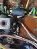
You know they use a spring inside that meter movement; as its' pivot point is a "jewel" designed to offer the least amount of friction but the spring is designed to apply tension to allow for some accuracy (a process of work) - in a lose term - but it will still have limits in displaying things properly using such a small face for you to glance and adjust your antenna SWR by.
So as you work between these two schematics, keep in mind that the meters used - have a different response to the amount of current - so you think you have it right, you can wind up burning out the meter movement because you placed too much current thru the coil and overheated it and damage the delicate aspects of the pivot and spring. So the Resistors and values used, are dependent on the meters power and current consumption - not so much effort to the accuracy to Bridge Impedance measurements - they only want you to see the power levels and too much reflection can destroy your radio.
- There is enough accuracy in the internal meter for a RATIO which then can be verified by an EXTERNAL SWR meter more dedicated to properly show impedance and SWR - don't sweat details - use the radio for it's purposes intended.
- It's why I mentioned the "Fly By The Seat Of Their Pants" because they knew they would have problems trying to squeeze a good dedicated metering system into the radio for detection and proper display - so they instead use a small known bridge reference for this power flow and it's direction and developed their own version of scaling using it.
So if you wanted to know why there is such a discrepancy, they placed more emphasis on the meters scale and face than keeping the meter and it's measurements true to faith of impedance measurement across a bridge.
The effort they did in keeping the current flow adequate enough to show full scale and measure it properly relied more on the meters face and needle position than the real actual impedance measurement.
So they selected resistors that act more conservatively in performing the task of SWR calibrate and then the reflection - measured across that circuit. They did the general calculations for you, they want you to pay attention to the RATIO of signal (OUT) to reflected (IN). THAT is what is more important, to keep the radio from having it's Finals blown.