• You can now help support WorldwideDX when you shop on Amazon at no additional cost to you! Simply follow this Shop on Amazon link first and a portion of any purchase is sent to WorldwideDX to help with site costs.
  • Click here to find out how to win free radios from Retevis!

Is resonance really where you get best antenna performance?

37 years of just plane old 'plug and play" antenna , coax and SWR meters , always doing my best for getting under 1.5 around the 11 meter band . Bottom line here is this ...........I just didn't know what I didn't know ......,but by the graces of the powers that be , I never blew up a radio or amplifier for not knowing any better and I think I had plenty of years to have done so . I suppose I'm just "one lucky guy" in this radio hobby ? If I had to have gotten this deeply involved with antennas and swr's I'm guessing I more then likely would have been gone a long time ago.
So maybe ? in the end of all of this , following the simple minded directions at least saved my radios and amplifiers ? (Thank God for that !) but I more then likely could have done so much better if I only had all the science down as I just got done reading for the last hour ? Yep ! I'm just one lucky guy ! (Thank you all for the antenna lesson) for me it's like this , if it works , whatever I do , dont fix it !
 
The shorter antenna designs - read this as less than 1/4 wavelength or like the 5K is shorter than a 102" whip - the "R" value changes - goes lower - when the antenna is shorter than it should be.

  • - it then has to add length by using inductance (coil wind) to restore that "X" value
  • - but it cannot compensate of bring the R-value back up to 50Ω
  • - to make the SWR Impedance closer to 50Ω the XL is added
    • - but adding that extra wire cannot bring back R except for being what the antenna "appears as" to the system - an antenna with a Lower R - which means it's offset by winds of wire to balance out Z to be closer to 50Ω
  • Your R value even though the antenna is shorter - helps to reduce the needs of the antenna having to REQUIRE extra wire because it can't make up the difference in height "Big R versus Little R ". - which helps reduce the dependence of Z (Impedance) requiring XL and XC having to make up the difference (your Conjugate used by the antenna)
After having read that, I'm glad my antenna doesn't suffer from low T!
 
  • Like
Reactions: wavrider
I adjust my antenna to the lowest possible swr, from the radio using the installed coax and forget it.
Never had any problems and never fried a radio.
And, had several really good talkers. Both local and skip. All of the other stuff mentioned here is WAY too complicated for me. Anyway, I do it how I do it, no problems at all. Ever.
yup, ALOT of people like to turn simple things into the most complicated, math driven, physics expert gibberish. the bottom line of antenna design is simple, build the antenna for resonance at the operating frequency, then match feedpoint impedance to transmission line using the appropriate method. done! that is the correct way to build an efficient antenna system. period
 
Now that I have a screwdriveron my car, I notice that if I tune by watching the rx meter and max sound that the see is always higher than if I use the see meter. And I've noticed resonance is never at lowest swr. I think the swr is always about 1.5 to 1.75. It's the feed point impedance I'm almost sure. If I remember right
 
The OP's write up is informative (even though I can't see his images), but seems to be missing a crucial piece of information that is missed by subsequent commenters. The OP says he "tunes for field strength"; O.K., that would be like making a 1/2λ vertical antenna a little longer, say to 5/8λ, because a 5/8λ antenna has greater field strength than a 1/2λ, or 1/4λ ground plane antenna, at the horizon, and it does, but even though the 5/8λ antenna is naturally not a resonant length, and if I remember correctly, it has an impedance & reactance of (75-425j)Ω, a good antenna designer, or radio operator, knows they have to bring that antenna into an impedance match with the rest of the radio system, typically 50 Ohms, otherwise they're gain at the horizon will be totally lost because of the impedance mismatch.

Another example is an end-fed half wave antenna which has a feed point impedance of between 2450-3600 Ohms, and is a resonant length, even though in a 50 Ohm system, your SWR is over 50:1. So, don't confuse resonance with impedance and reactance. Any resonant or non-resonant antenna length, can be brought into a perfect impedance match with the radio and coax, and must be matched for the optimal power transfer. The fact that the OP achieves a more desirable radiation pattern by his method of tuning is great, but after getting the pattern he wants, he can then use his Nano-VNA to figure out how to get a perfect impedance match to the rest of his system, by adding series or parallel capacitance or inductance, and/or a tuning stub.

Folks who tune for the lowest SWR are certainly doing the right thing if that is the only instrument you have, but for someone as serious as the OP, he's on the right track in optimizing his pattern for the effect that he wants.
 
(even though I can't see his images)

If you look under DX Gallery link above and click on my name, in there is an album called "Does resonance show max gain?" This has the images that were used in the initial post of this thread. Back when I posted it, I was able to link the images in an album on this forum directly into a post. Unfortunately, those old links no longer connect, it happened during a forum update a while back which changed it to directly inserting the images used into the post.

Also, Harry. What you mentioned about antenna length overall is true, however, I think in this case there is an issue of scale. When it comes to tuning antennas, we do not changing between 1/4, 1/2 and 5/8 wavelengths in length, instead we use very small, fractios of a wavelength. A lot of instructions that comes with antennas talk about making cuts of 1/8 of an inch or less when tuning. What fraction of a wavelength is that at 27MHz? It is true that there will be very small (essentially at an insignificant level) changes in the antenna's radiation pattern, so sure, it will play a part here, but it will be a very small to insignificant part as other aspects (and variables) of and related to the antenna are changing much faster.

Folks who tune for the lowest SWR are certainly doing the right thing if that is the only instrument you have, but for someone as serious as the OP, he's on the right track in optimizing his pattern for the effect that he wants.

This is more related to something Freecell said on this forum in the past but I'm not going to fish out that quote.

I've actually been experimenting with my tunes again recently (since covid). I took a spectrum analyzer (the kind that plugs into the computer) and stream the output online using twitch. I then use a laptop connected to a mobile internet connection to read that data on-site. This allows me to test a mobile tune in multiple locations in various directions. Long story short, what I have found is at least for local communications, it seems that the tune I described above using a second antenna attached to my nano-vna's second port as measured 100 feet away is confirmed for mobile measurements as tested from various locations and directions between 5 and 20 miles away from the shack.

Again, as I essentially posted above, this is just me being picky and pushing my knowledge. You won't notice the difference between this tune and tuning using SWR or resonance. There just isn't enough of a difference in output between said tunes to make any real difference...

The idea was inspired by an observation I made from a heated debate that has since been resolved between two other members of this forum, Marconi and Shockwave. I noticed after the fact that they were using two very different ways of measuring data to support their arguments. So thanks to both of you as various realizations from said debate from years ago are still bringing ideas to me, even if I'm not using the antenna in question...


The DB
 
  • Like
Reactions: AudioShockwav
Gonna drop this here on page 9 as a Recap and ain't nobody got time to re-read all this.
The OP asks about "Best Performance"
Now that depends on what your definition of {performance} is. What operational parameter is most important to your preferred style of operating?
Is Local Talking most important to you? If so, then you want Highest Gain. Here your true 5/8wave will direct the most signal towards the horizon. You'll get the biggest signals out to the furthest distances. All other considerations like cost and physical installation for the greater length being okay with you, the only "drawback" to a 5/8 is less overall bandwidth with no swr. You get more bandwidth going down to a 1/2 wave and get the most bandwidth out of a 1/4 wave.
The greater bandwidth at No SWR may be important if you like to operate all over the band up and down and perhaps are running an SWR-Sensitive amplifier where it is important to have little to no swr and you don't want to run an SWR-Corrective Antenna Tuner.
Pretty much all verticals can be tuned/adjusted for Resonance and little to no SWR as long as there's nothing wrong with the antenna or your feedline.
 
  • Like
Reactions: Crawdad7
I've actually been experimenting with my tunes again recently (since covid). I took a spectrum analyzer (the kind that plugs into the computer) and stream the output online using twitch. I then use a laptop connected to a mobile internet connection to read that data on-site. This allows me to test a mobile tune in multiple locations in various directions. Long story short, what I have found is at least for local communications, it seems that the tune I described above using a second antenna attached to my nano-vna's second port as measured 100 feet away is confirmed for mobile measurements as tested from various locations and directions between 5 and 20 miles away from the shack.

Again, as I essentially posted above, this is just me being picky and pushing my knowledge. You won't notice the difference between this tune and tuning using SWR or resonance. There just isn't enough of a difference in output between said tunes to make any real difference...

The idea was inspired by an observation I made from a heated debate that has since been resolved between two other members of this forum, Marconi and Shockwave. I noticed after the fact that they were using two very different ways of measuring data to support their arguments. So thanks to both of you as various realizations from said debate from years ago are still bringing ideas to me, even if I'm not using the antenna in question...


The DB
Great, I saw your images.
Yes, I noticed that the far-field plots had <1dB difference; I don't think those scenarios are going to be detectable outside of laboratory conditions & instruments.
About your graphs though, the modeling software I've used, EZ-NEC & MMANA-GAL, don't consider source impedance or reactance in their gain calculations, so if you are modeling for a certain radiation pattern of an antenna at a given frequency, to actually get that calculated gain, you need to match the feed-point impedance of the antenna to the rest of your system, are you doing that?
(For people following along) In other words, if you want the 2.15 dBi theoretical gain of a 1/2λ dipole over an isotropic radiator, for a 50Ω system, in practice, you'll only get 2.15 dBi gain if your antenna feed-point impedance is also 50Ω; If you have an input impedance of 73Ω (which is what a dipole has in "free-space"), that would create a 1.46:1 SWR, and your gain would not be 2.15.
So I'm curious if that is taken into consideration in your graphs of Gain & SWR?
http://gal-ana.de/basicmm/en/

 
I don't think those scenarios are going to be detectable outside of laboratory conditions & instruments.

I've said several times in this thread and elsewhere that you won't notice the difference between however you choose to tune your antenna, included in that quoted post. Part of the point of the thread was to challenge a concept that is widespread but no one has ever demonstrated before.

About your graphs though, the modeling software I've used, EZ-NEC & MMANA-GAL, don't consider source impedance or reactance in their gain calculations, so if you are modeling for a certain radiation pattern of an antenna at a given frequency, to actually get that calculated gain, you need to match the feed-point impedance of the antenna to the rest of your system, are you doing that?

The models were done in 4nec2, however, the data was converted to data in Libreoffice Calc (essentially a spreadsheet like excel) as I later added data that the modeling software did not have the ability to add. That data came from this web site. On the chart that compares raw gain to gain after the effects of an impedance mismatch of two different pieces of feed line with different loss characteristics.

There are no matching circuits here. I am well aware of how they work, but they are not relevant here. There are a group of antennas that don't use matching circuits, and those are the antennas targeted in this post. The model was a center fed dipole. The resonance equals maximum gain is a claim on antennas that are not used with matching circuits, such as the dipole (modeled above) or any number of mobile CB antennas and others, a claim that I not only couldn't find any evidence to support, but all the evidence I have actually found disagree with. This thread was more or less challenging that concept with evidence.

Could you add a matching circuit to these antennas? Yes, but how many people actually do?

(For people following along) In other words, if you want the 2.15 dBi theoretical gain of a 1/2λ dipole over an isotropic radiator, for a 50Ω system, in practice, you'll only get 2.15 dBi gain if your antenna feed-point impedance is also 50Ω; If you have an input impedance of 73Ω (which is what a dipole has in "free-space"), that would create a 1.46:1 SWR, and your gain would not be 2.15.
So I'm curious if that is taken into consideration in your graphs of Gain & SWR?

This is absolutely true. Let me repost a pic from that post here.

bcb0d9610a871583d95c35df0df28942.jpg

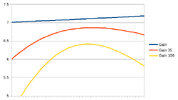
This chart shows not only the raw gain data of the 4nec2 modeling software, but the effects on said gain after factoring in the feed point impedances plus, for the red line 35 feet of LMR-400, and the yellow line we used 100 feet of LMR-400. The impedance data was provided by the coax loss calculator on the QSL.net web site. The whole point of this was to show that happens when you have a changing impedance over a frequency range, and a feed line added in.

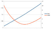
Taking that, and adding in the data from this image (also from said post) which shows the gain of the antenna from the modeling software in relation to its SWR.

8143acbbd860fd4330141e05f1ae4a90.jpg

The blue line is the same gain from the image above, its values are on the left of the image. The red line is SWR, its values are on the right of the image.

These two pictures together demonstrate that once you have an impedance mismatch, and some length of feed line, the peak gain of the antenna system moves towards the low SWR point (not the resonant point). The more loss in said coax (and it doesn't take much) the more this effect pushes the max gain point towards the low SWR point.

*****

And I feel I should add in again, for the umpteenth time, in the so called "real world" and really in generally accepted "theory" as well, when it comes to tuning you will not notice the difference between any of these tuning points, so use what you want, it really doesn't matter. There is no need to get fancy equipment and tune for this or that (such as resonance for in my case, peak field strength) unless you are having difficulty tuning said antenna. If you just want to make contacts and have conversations, local or otherwise.


The DB
 

dxChat
Help Users
  • No one is chatting at the moment.
  • @ Deon:
    Good day, I have an Icom IC910H radio. I want to program a memory with split frequency tone on TX only and NO tone on RX,. Is this possible to do from the face of the radio? I don't have the interface to connect to a computer.
  • @ crappykraco:
    @Deon very unlikely to get a response here. You are better off starting a thread on the topic.
  • dxBot:
    Backwoods40 has left the room.
  • dxBot:
    GlocknSpiel has left the room.