• You can now help support WorldwideDX when you shop on Amazon at no additional cost to you! Simply follow this Shop on Amazon link first and a portion of any purchase is sent to WorldwideDX to help with site costs.

KLV-550

c34-36 are decoupling caps, increasing the value won't hurt but it won't fix it either,

i will explain whats happening with the kl550's i have seen,

in standby or keyed in ssb mode with no audio
tr8 is turned on shunting the base voltage from r30 to tr9 ( bias pass transistor ) to ground turning the bias off,

tr8 gets its base voltage through r29,

r29 gets its voltage through r6 in parallel with rl2 ( the antenna relay coil ),

tr8 / rl2 and the second cooling fan are switched via tr3 (keying transistor ),

as you start talking on ssb a portion of rf is rectified by d4-d5 and applied to the base of tr3,

as tr3 starts conducting it provides a path to ground for the cold side of relay rl2 and the second cooling fan which also starts reducing the base voltage seen at tr8,

at a certain low drive level tr3 is conducting enough to pull in rl2 and turn on cooling fan2 but not conducting hard enough to reduce the base supply seen at tr8 below its turn-on voltage causing the amplifier to be inline with zero bias and distorted ssb audio,

as you increase drive tr3 turns on harder reducing base voltage seen at tr8 and tr8 turns off causing tr9 to turn on applying bias to the final transistors,

bias supply should be turned on just before or at the same time as the antenna relay pulls in, never after the relay pulls in as seen in the kl550,

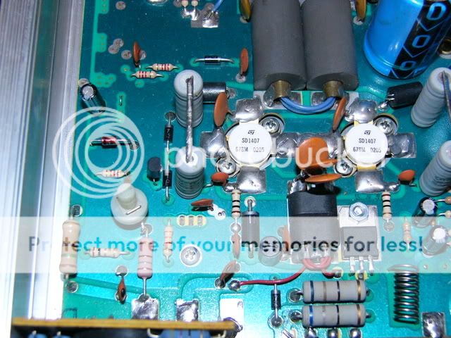
the resistor i added connects from tr8 side of r29 to ground forming a potential divider that reduces the base voltage at tr8 so that tr3 does not need to be conducting so hard to turn tr8 off and tr9 on,

i tacked the variable in the pic onto the grounded side of r17 because it was an experiment and i did not want to scrape the foil to make a ground connection before i knew it worked,

afaik the 550's i have fixed are the only 550's that sound ok on ssb.
 
Ahh, no what if you just remove cooling fan 2, and hook it up with cooling fan 1 and have the 2 run together. giving more to tr8? I guess dropping the value of r5 in front of tr3 wouldn't help? I am learning a bit here about this amp, thank you for this!
 
d'oh, :oops:I read it while talking skip with the UK, lol. Sorry. I saw how the fan needed tr3 to conduct ground to turn on the fan. I figured if I pulled the fan out, it could conduct more to reduce the base supply voltage at tr8.
 
no worries, im in the uk, just turned the radio on listening to usa, sounds like its getting time to put something in the car and head to the fields for some stateside dx;)
 
yeah man. Ill be getting out there later to try your resistor trick again. I had a pot that went from 0 to 5k, tried from 40 ohms up, didn't seem to make a difference though, I guess I should try a lower value.

Maybe I'll get some more UK skip. I am 231 in South Eastern PA

FWIW, the revision 500 uses a different TR9, a BD241. while revisions 300 and 301 at least use the BD179.
 
Last edited:
never seen the version 5.00, i have seen the larger pass transistors in the later revision kl400 and kl500 mobile amps,
i think UK shops stopped selling the 550 base amps when the price got too high.
 
never seen the version 5.00, i have seen the larger pass transistors in the later revision kl400 and kl500 mobile amps,
i think UK shops stopped selling the 550 base amps when the price got too high.

I can get one from Newark. Looking at the schematic, the values of the other parts around it are the same. So, I think I will order one and try it out. I haven't really heard from anyone with revision 500, but I read somewhere the bias issue was improved? Wish i could find where I read it. But, I made all the values of the de-coupling caps, and a few others, the same as revision 500 (SD1407's), the last thing would be tr9.

My antenna relay engages pretty much right away when I key up in SSB, so trying to read the .65vdc or so at L9 is like super difficult, lol
 
Well, what I did was get some little jumper wires, and hooked on to ground, and the other to the base or TR8. Then a 5k pot to the jumpers. I used my fluke to measure voltage right at the junction of l9 and c36. now thru this whole process, I never saw more than .33vdc on the fluke. So, with a friend pretty close, I moved the pot around, he said 5k sounded better, so i added a 5k ohm resistor in series to the pot, and turned the pot to 0, and worked up. then I got to 10k, it sounded better, the I took out the 5k and put a 10k in series, turned the pot to 0, and worked up till I got about 13.3kohm and he said it is the best it sounded. I went to 15kohm and it sound a bit worse he said.

Again, I never saw .6vdc on anything from 10ohms all the way to 15k. So, I dunno, but it apparently sound better. I have both fans running all the time too, fan 2 never comes on, even when talking full power getting 380-400PEP on SSB. I wonder if IC1 is bad, or TR8 is just going bad or is bad.

I am ordered the BD241C from Newark. I don't know if the revision 500 has BD241A, B or C. not sure what the difference is between them all. And maybe by Friday I'll have it here to try out. its only like $0.66, and a 10 pack of TO-220 style mica insulators, enough for some for my president, and a heatsink for it just in case.
Any thoughts?
 
Last edited:
the bd179 is a smaller package and fits under the board, the 241 won't fit the older boards,

are you measuring bias on top of the choke? .33v is no good at all

have you modded the fan setup? only 1 should run untill you key up,
if ic1 the fan regulator was short the fans would be getting close to 30v,

what else besides the transistors have you changed?

post a closeup pic of the board,
you will have to take some measurements to find out where the fault is

P1010306.jpg
 
Well, when I got the amp it was modded for 2sc2879 pills, both were no good. There were a few resistors on the power selector that were all burned up, probably from overdriving it. I have revision 301, so it should have had MRF422's. What I did, was make it more like revision 500. I added R16, R17 and C23 for the lower drive SD1407's. Revision 500 had some higher value disc caps, c11,c27,c29,c34 and c36 were 10nF, I made the 100nF like revision 500. It's got new r24 and r27, new r11, new r25 and r26. I bunch of diode were clipped and soldered back together. 1N4148's So I replaced those. D,2,4,5,11,12,13,14,19,20,21. I also replaced RL1, it was making a weird noise.

I was measuring voltage at the top of L9 and at the L9-C36 junction, same voltage readings with the fluke.

if the 241 won't fit under, I'll put it on top. tha is why i got the extra TO-220 style heat sink.
 

Attachments

  • downsized_1005011307.jpg
    downsized_1005011307.jpg
    27.1 KB · Views: 107
  • downsized_1005011306.jpg
    downsized_1005011306.jpg
    33.6 KB · Views: 104
sounds like you are halfway to rebuilding it lol,

check all the resistors in the bias circuit and d15 16 17, make sure r25 26 are 10ohm, with s3 closed you should have about 30v on r28
 
yeah, i am. I just ordered replacement transistors for the whole thing from H&Y, i'll check the voltages tonight in a few minutes and post the results. I may put a variable resistor at r-29, the resistor right before tr8, to try and get the voltage dropped so it turns off, maybe that'll help?

The diodes and resistors in the bias circuit are good, I have about 31.5 vdc on r28.

I was thinking, since fan number 2 works with the ground right to ground, but never comes on when hooked up normal, even when keyed and talking in and power position, if TR8 is bad? If TR8 is NFG, then the fan would never get a ground potential.
 
Last edited:
tr3 grounds fan2 and the base of tr8 to turn fan2 on and tr8 off, fan2 usually comes on before the bias is fully up to voltage, if d18 is ok and fan2 won't turn on when you connect it as shown on schematic but works when you ground it the bias won't turn on either,
you can lift r29 and use s3 to turn the bias of and on for testing purposes, you should see at least .6v dc on the bias choke
 
ok, that makes sense. You;ll have to forgive me, it is taking a while for it all to come back, lol. Been an electrician on A-10 jets for too long, analog era stuff, lol. i'll get out there in the morning and try it all out

With my fluck, the diode d18 reads good. but I ordered all new transistors from H&Y, they were super cheap, and the rest of the diodes for it I didn't have. can't hurt to have spare parts, lol.
 

dxChat
Help Users
  • No one is chatting at the moment.
  • dxBot:
    Tucker442 has left the room.
  • @ BJ radionut:
    LIVE 10:00 AM EST :cool:
  • @ Charles Edwards:
    I'm looking for factory settings 1 through 59 for a AT 5555 n2 or AT500 M2 I only wrote down half the values feel like a idiot I need help will be appreciated