
I should start out by warning anyone who agrees to fix a pre-1990 Galaxy Saturn that you'll find lots of stuff wrong.
How do you tell it's old? If it has the large metal can housing the frequency counter, running along the side rail behind the speaker? That makes it before 1995.
And if it has the circuit-board number printed in foil just to the front from the TA7222P audio chip like this?
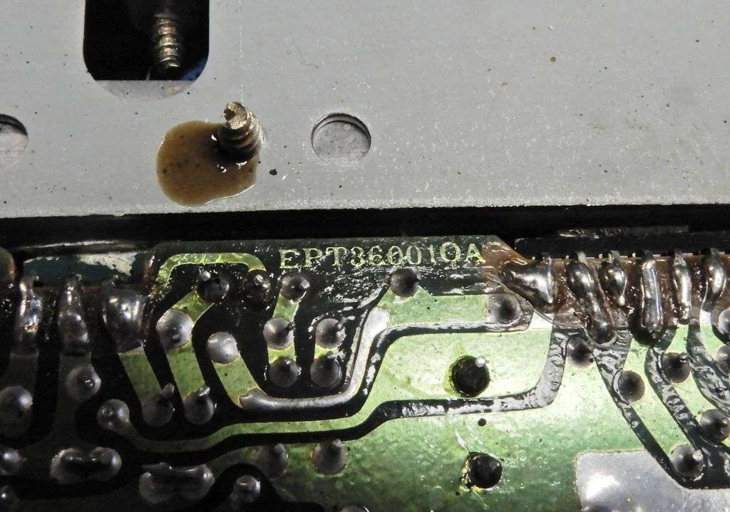
The "10A" suffix makes it before 1990 or '91. And those are just more trouble prone. And if the "EPT" circuit-board number appears along the frontwards edge of the pc board, it's newer than this one.
One major annoyance was the spontaneous failure of front-panel controls, like the mode selector, RF Power, volume or RF Gain/Mike gain. The control just goes bad. No amount of cleaning will bring it back. And the shafts are longer than most stock replacement controls.
But in the rant department, failed "cans", or slug-tuned IF/RF coils is a close second. I suspect that humidity exposure has a lot to do with it. The built-in capacitor inside these will fail. Just becomes an open circuit.
Won't be intermittent at all. Once it quits, that slug won't tune any more. Kills transmit power, receiver sensitivity or both.
One saving grace of the cans with the thin threaded tuning slug is that they will appear to have a broad peak response with the slug positioned DEAD EVEN with the rim of the hole. If you see this, you can hack a fix without tracking down a replacement for a "12010" IF coil or whatever.
The hack is to solder a trimmer capacitor across the two pins of the coil where the cap is attached inside. Tricky part is to find out what the capacitance value if that internal cap used to be. Not marked on the schematic. And the dirty trick for doing this would require desoldering of a good part that hasn't gone bad yet to make a measurement. The trimmer cap will, we hope take the place of the failed fixed cap and permit the tuning slug to respond as it did before the failure.
Never have quite gotten around to that.
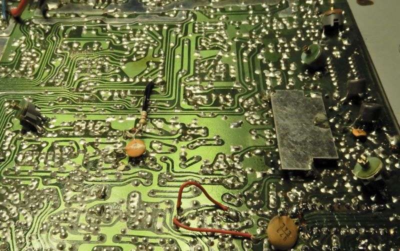
This radio has chips dated 1987 in it, or did before I replaced some of them. It has six trimmer caps scabbed onto the solder side of the main circuit board. That's how many cans would not tune to a peak. You could call this kind of radio "hand-to-hand" troubleshooting.
After all this, the radio still had psychotic tendencies. The frequency on the display would spontaneously jump down to 25 MHz and only lock back in if you turned the band selector to band "A". Clicking it back up to band C would only hold for a moment before it popped out of lock. After checking the peak on L16, it acquired a really baffling symptom.
5 kHz channels. Yeah, it would only advance 5 kHz for each click of the channel selector, not ten like it should.
It would lock in and appear more or less stable, but with the channels half as far apart as they should be.
Figured it had to be the PLL chip. Changed it. No difference. The 4008 adder chips that translate the band selector to the binary numbers that feed the PLL will famously act up for no reason I can see. Changed them.
No change. At all.
I'll skip the part about frustrated hair-pulling and cut to the chase. All but one of the slug-tuned coils seen in the pic above will affect either transmit power or receiver signal level when the slug is turned.
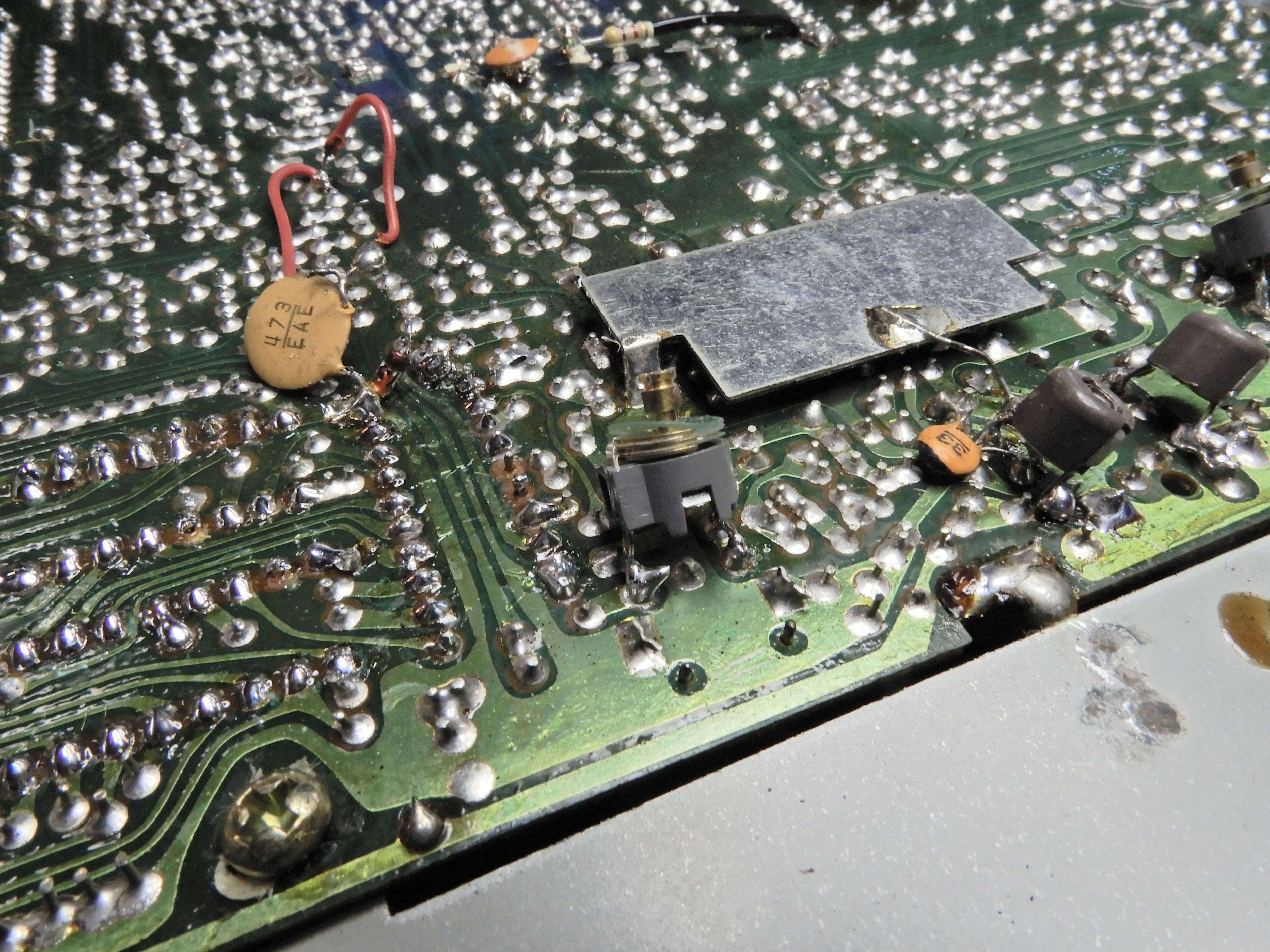
But this radio's PLL circuit has a tuned circuit with one of these slug tuned coils L16 between the 14.460 MHz band crystal and the mixer transistor that combines it with the radio's VCO. The difference frequency between the two is what feeds into the PLL's input pin. And that's the only place you can clearly see a peak from the slug of L16 is on pin 2 of the PLL chip.
Turns out the problem is a failed cap inside L16. The slug appeared to show a peak, looking at the input to the PLL's pin 2 on a 'scope. That peak was occurring at a frequency much higher than the 14.460 MHz it's meant to pass through. Apparently a sufficiently-high frequency to give the PLL a headache. Long story short, adding that sixth trimmer cap to L16 restored the "correct" peak to the coil's tuning slug.
Just couldn't use the Saturn's S-meter or transmit output to peak it. Just had to "tune in" the 14.460 from the band crystal with a receiver then peak the S-meter with the trimmer cap, and fine tune with the slug.
One clue was that probing pin 2 of the MC145106 PLL chip with a 'scope probe would knock the PLL out of lock. Shouldn't do that. Once L16 was tuned in the ballpark, touching the 'scope probe's tip to pin 2 permitted a proper peak setting of L16 without disturbing the circuit's lock state.
Just goes to show that no matter how many hundred radios of one kind you fix up, you'll never see it all.
And if you find a EPT360010A-based radio that only advances 5 kHz for each click of the channel selector, you'll know where to look next for the culprit.
For that matter, if someone asks you to fix a pre-1990 Saturn radio, just reply with a loud "CHA-CHING!".
Or the Dracula sign.
73
How do you tell it's old? If it has the large metal can housing the frequency counter, running along the side rail behind the speaker? That makes it before 1995.
And if it has the circuit-board number printed in foil just to the front from the TA7222P audio chip like this?
The "10A" suffix makes it before 1990 or '91. And those are just more trouble prone. And if the "EPT" circuit-board number appears along the frontwards edge of the pc board, it's newer than this one.
One major annoyance was the spontaneous failure of front-panel controls, like the mode selector, RF Power, volume or RF Gain/Mike gain. The control just goes bad. No amount of cleaning will bring it back. And the shafts are longer than most stock replacement controls.
But in the rant department, failed "cans", or slug-tuned IF/RF coils is a close second. I suspect that humidity exposure has a lot to do with it. The built-in capacitor inside these will fail. Just becomes an open circuit.
Won't be intermittent at all. Once it quits, that slug won't tune any more. Kills transmit power, receiver sensitivity or both.
One saving grace of the cans with the thin threaded tuning slug is that they will appear to have a broad peak response with the slug positioned DEAD EVEN with the rim of the hole. If you see this, you can hack a fix without tracking down a replacement for a "12010" IF coil or whatever.
The hack is to solder a trimmer capacitor across the two pins of the coil where the cap is attached inside. Tricky part is to find out what the capacitance value if that internal cap used to be. Not marked on the schematic. And the dirty trick for doing this would require desoldering of a good part that hasn't gone bad yet to make a measurement. The trimmer cap will, we hope take the place of the failed fixed cap and permit the tuning slug to respond as it did before the failure.
Never have quite gotten around to that.
This radio has chips dated 1987 in it, or did before I replaced some of them. It has six trimmer caps scabbed onto the solder side of the main circuit board. That's how many cans would not tune to a peak. You could call this kind of radio "hand-to-hand" troubleshooting.
After all this, the radio still had psychotic tendencies. The frequency on the display would spontaneously jump down to 25 MHz and only lock back in if you turned the band selector to band "A". Clicking it back up to band C would only hold for a moment before it popped out of lock. After checking the peak on L16, it acquired a really baffling symptom.
5 kHz channels. Yeah, it would only advance 5 kHz for each click of the channel selector, not ten like it should.
It would lock in and appear more or less stable, but with the channels half as far apart as they should be.
Figured it had to be the PLL chip. Changed it. No difference. The 4008 adder chips that translate the band selector to the binary numbers that feed the PLL will famously act up for no reason I can see. Changed them.
No change. At all.
I'll skip the part about frustrated hair-pulling and cut to the chase. All but one of the slug-tuned coils seen in the pic above will affect either transmit power or receiver signal level when the slug is turned.
But this radio's PLL circuit has a tuned circuit with one of these slug tuned coils L16 between the 14.460 MHz band crystal and the mixer transistor that combines it with the radio's VCO. The difference frequency between the two is what feeds into the PLL's input pin. And that's the only place you can clearly see a peak from the slug of L16 is on pin 2 of the PLL chip.
Turns out the problem is a failed cap inside L16. The slug appeared to show a peak, looking at the input to the PLL's pin 2 on a 'scope. That peak was occurring at a frequency much higher than the 14.460 MHz it's meant to pass through. Apparently a sufficiently-high frequency to give the PLL a headache. Long story short, adding that sixth trimmer cap to L16 restored the "correct" peak to the coil's tuning slug.
Just couldn't use the Saturn's S-meter or transmit output to peak it. Just had to "tune in" the 14.460 from the band crystal with a receiver then peak the S-meter with the trimmer cap, and fine tune with the slug.
One clue was that probing pin 2 of the MC145106 PLL chip with a 'scope probe would knock the PLL out of lock. Shouldn't do that. Once L16 was tuned in the ballpark, touching the 'scope probe's tip to pin 2 permitted a proper peak setting of L16 without disturbing the circuit's lock state.
Just goes to show that no matter how many hundred radios of one kind you fix up, you'll never see it all.
And if you find a EPT360010A-based radio that only advances 5 kHz for each click of the channel selector, you'll know where to look next for the culprit.
For that matter, if someone asks you to fix a pre-1990 Saturn radio, just reply with a loud "CHA-CHING!".
Or the Dracula sign.
73
Last edited:
