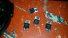
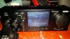
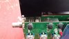
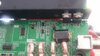
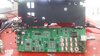
on my bench..the mosfets are replaced and upto now its TX per specs..But I was itching to measure voltage but didnt dare to..usually these radios are calibrated by measuring current draw at the DC..anybody would happen to know voltages on the fets?

-
You can now help support WorldwideDX when you shop on Amazon at no additional cost to you! Simply follow this Shop on Amazon link first and a portion of any purchase is sent to WorldwideDX to help with site costs.
-
A Winner has been chosen for the 2026 July 4th Retevis RA89R Giveaway! Click Here to see who won!
M0nka derived SDR-928 finals voltage
- Thread starter codecxbox
- Start date
")