
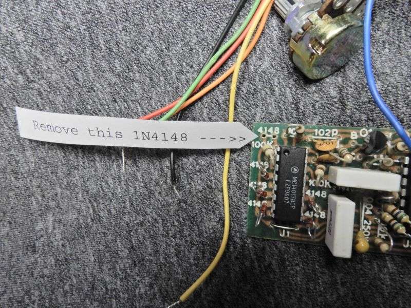
So here's a how-to that's probably 20 years too late. The Roger-K board shown here has sold out permanently everywhere we ever got them. In the early 90s a customer talked me into making an unkey noise nobody else had. Started out as a "Roger K" that puts a morse-code letter "K" on your signal as a roger beep. Dash-dot-dash. Removing one diode from the board removed the "dot" making it a dash-pause-dash.
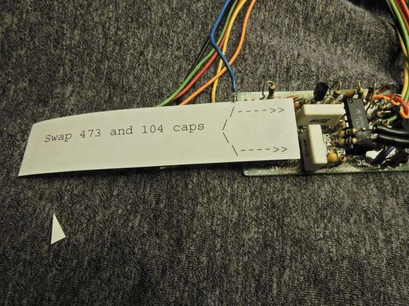
The duration is pretty short, around 1/3 of a second. The capacitor in the timing circuit that sets the speed of the thing is a .047uf film cap. The audio output of the board uses a DC-blocking capacitor with a 0.1uf value. Swapping these two caps will double the length of the beeps and won't have much effect on the overall sound.
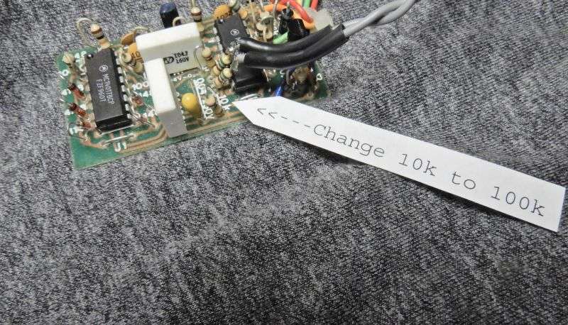
Two resistors get changed to boost the audio output level. Changing the pitch will also change the audio-output level. A low pitch will get attenuated and this will compensate for that.
First change this 10k at the edge of the board to 100k. The boards we bought had a white screen-print legend on the component side. They didn't use schematic-diagram style "callout" numbers "R", "C", etc. Just the component's actual resistance or capacitance value.
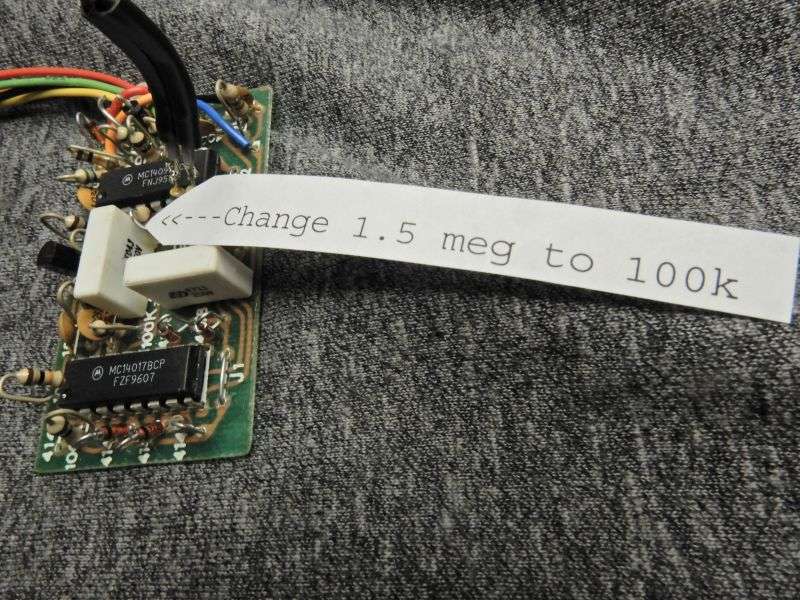
Another resistor farther in from the edge is marked "1.5M". It gets changed to 100k.
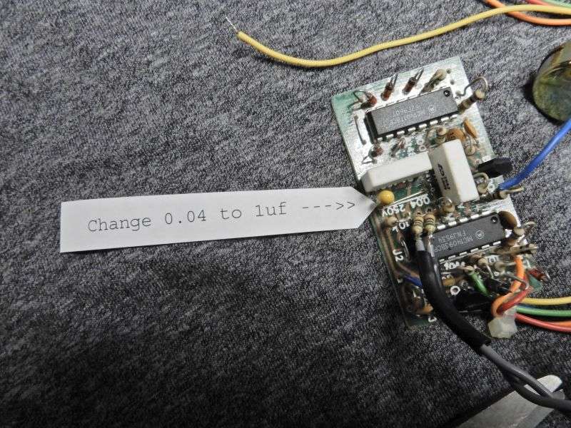
Now we come to the parts that set the pitch of the beep tone. The original cap that does this has a value of .04uf, and is a "dipped" style part, not the square-edged box shape of the two white capacitors. It gets replaced with a 1uf part. We used a small tantalum cap. The type used doesn't seem to be critical. If you use a tantalum, just make sure to keept the polarity correct. The side of this cap at the outer edge of the board is the negative side.
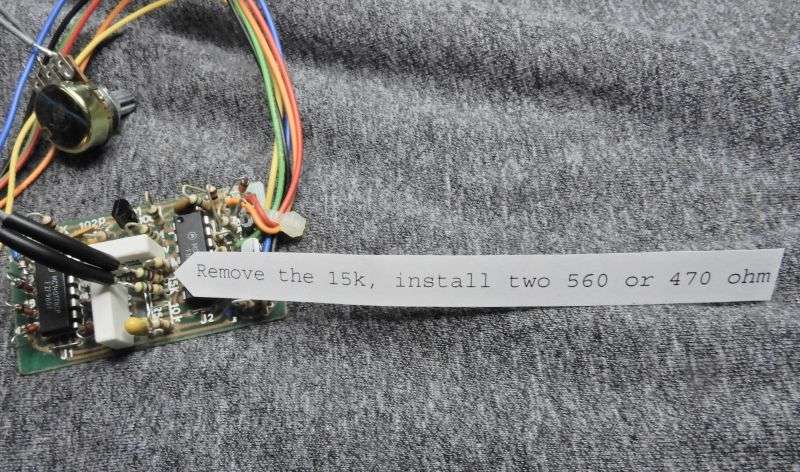
Alongside this cap is a 15k resistor. Didn't get a clear pic of that marking, but you'll see it. This resistor gets removed. A 560 ohm resistor is inserted into each of the two holes it came out of.
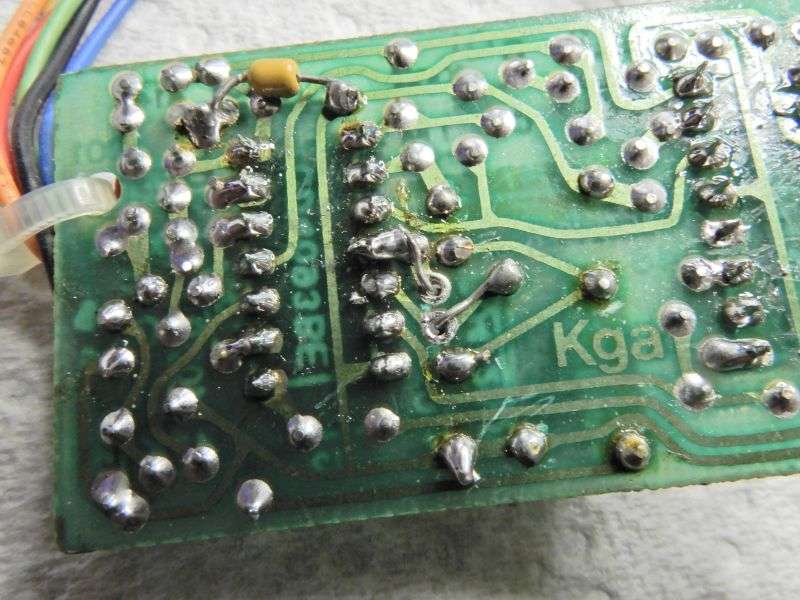
I recommend you don't just solder these resistor leads to the edge of the holes where they pass, but lay the lead down to reach the nearest solder pad at the other end of that foil trace. The foil on this board is incredibly thin and will come loose from the laminated with the slightest force applied. Passing the lead around the hole where it passes through and soldering it farther down takes the torque off the foil pad.
The tiny capacitor at the upper left is a 0.1uf that is soldered to the pad where the orange wire is attached on one end. The other end is grounded. This cap serves to prevent any nearby RF from entering the board's circuit by way of that orange wire. Grounding the orange wire shuts down the beep. But when it's not grounded, it can become an antenna for stray transmitter RF voltage. This cap prevents whacko behavior that RF pickup on the orange wire can cause.
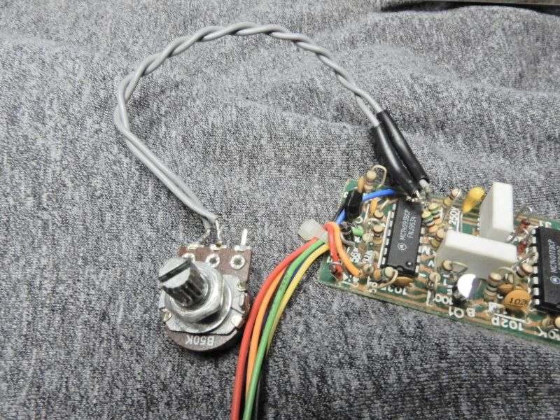
The pitch control we use is a 50k linear pot. This matches the squelch knob used in most RCI-built base radios. In a Saturn or 2980 the PA switch on the squelch knob may be hijacked and connected to the orange wire to shut the beep off, and set pitch with the squelch knob.
The first pitch mod we used had a 500k pot and a capacitor roughly 1/10 of a microfarad. Hijacking the radio's 50k squelch knob called for a larger cap. Your mileage may vary.
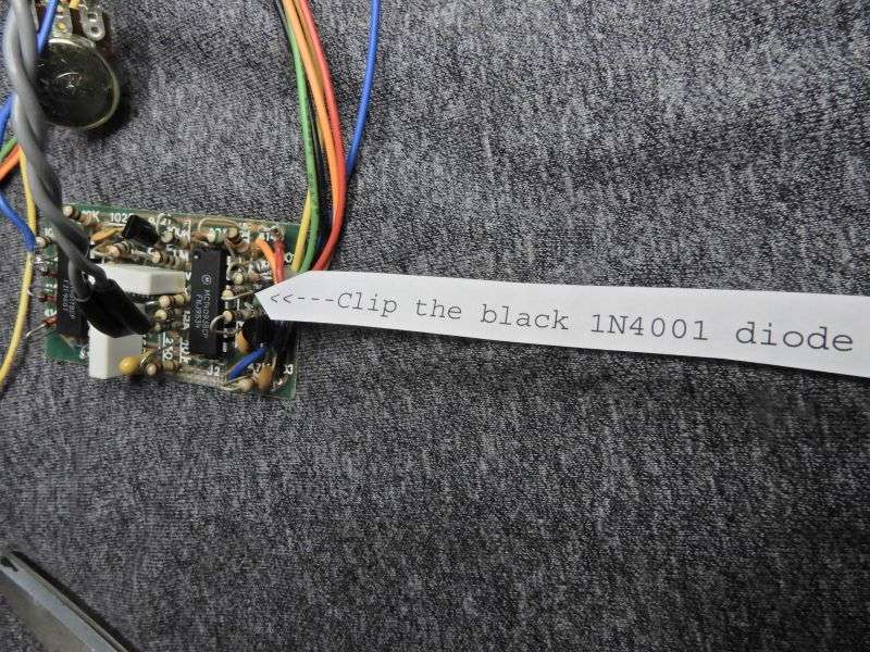
Lastly, I recommend using the radio's regulated 9 Volt supply to power the red wire on this board. Less chance of noise or feedback sneaking into the transmit audio.
This will call for clipping or removing a black 1N4001 1-Amp rectifier diode, found near where the wire bundle is zip-tied to the board.
This isn't meant to be directions to install the thing, but here's the color coding of the wires.
Orange: shuts down the beep when grounded, allows the beep when it's not connected.
Red: power, preferably regulated 8 Volts/9 Volts DC.
Black: ground. Connect to the mike socket's ground, or ground foil alongside the radio's mike amp circuit.
Green: keying input. The wire to the keying pin of the radio's mike jack gets disconnected from the jack. The green wire goes in its place.
Yellow: keying output. The wire you removed from the mike jack goes to this wire.
Blue: audio output. Can go to the audio pin of the mike socket, or to some point downstream. Always more than one way to skin that cat. Connecting it downstream from the mike gain control will allow a loud bump no matter the mike gain setting. Connecting it too far downstream from the mike gain control could get you odd clicking noises from the board's sequence oscillator.
One more detail. Hooking the blue wire to the audio pin of the mike jack can create trouble if you use an older 4-wire D104 mike. The TUG-8 base would switch the audio wire to ground in receive mode. This will dead-short the beep audio when the mike unkeys. Clipping a wire inside the mike fixes this. Don't remember what color it is.
So there's what you need to know for converting a roger beep you can't buy into a bump-bump you can't buy.
Yeah, these turn up from time to time. They're not really extinct, but just rare as hens' teeth.
73
The duration is pretty short, around 1/3 of a second. The capacitor in the timing circuit that sets the speed of the thing is a .047uf film cap. The audio output of the board uses a DC-blocking capacitor with a 0.1uf value. Swapping these two caps will double the length of the beeps and won't have much effect on the overall sound.
Two resistors get changed to boost the audio output level. Changing the pitch will also change the audio-output level. A low pitch will get attenuated and this will compensate for that.
First change this 10k at the edge of the board to 100k. The boards we bought had a white screen-print legend on the component side. They didn't use schematic-diagram style "callout" numbers "R", "C", etc. Just the component's actual resistance or capacitance value.
Another resistor farther in from the edge is marked "1.5M". It gets changed to 100k.
Now we come to the parts that set the pitch of the beep tone. The original cap that does this has a value of .04uf, and is a "dipped" style part, not the square-edged box shape of the two white capacitors. It gets replaced with a 1uf part. We used a small tantalum cap. The type used doesn't seem to be critical. If you use a tantalum, just make sure to keept the polarity correct. The side of this cap at the outer edge of the board is the negative side.
Alongside this cap is a 15k resistor. Didn't get a clear pic of that marking, but you'll see it. This resistor gets removed. A 560 ohm resistor is inserted into each of the two holes it came out of.
I recommend you don't just solder these resistor leads to the edge of the holes where they pass, but lay the lead down to reach the nearest solder pad at the other end of that foil trace. The foil on this board is incredibly thin and will come loose from the laminated with the slightest force applied. Passing the lead around the hole where it passes through and soldering it farther down takes the torque off the foil pad.
The tiny capacitor at the upper left is a 0.1uf that is soldered to the pad where the orange wire is attached on one end. The other end is grounded. This cap serves to prevent any nearby RF from entering the board's circuit by way of that orange wire. Grounding the orange wire shuts down the beep. But when it's not grounded, it can become an antenna for stray transmitter RF voltage. This cap prevents whacko behavior that RF pickup on the orange wire can cause.
The pitch control we use is a 50k linear pot. This matches the squelch knob used in most RCI-built base radios. In a Saturn or 2980 the PA switch on the squelch knob may be hijacked and connected to the orange wire to shut the beep off, and set pitch with the squelch knob.
The first pitch mod we used had a 500k pot and a capacitor roughly 1/10 of a microfarad. Hijacking the radio's 50k squelch knob called for a larger cap. Your mileage may vary.
Lastly, I recommend using the radio's regulated 9 Volt supply to power the red wire on this board. Less chance of noise or feedback sneaking into the transmit audio.
This will call for clipping or removing a black 1N4001 1-Amp rectifier diode, found near where the wire bundle is zip-tied to the board.
This isn't meant to be directions to install the thing, but here's the color coding of the wires.
Orange: shuts down the beep when grounded, allows the beep when it's not connected.
Red: power, preferably regulated 8 Volts/9 Volts DC.
Black: ground. Connect to the mike socket's ground, or ground foil alongside the radio's mike amp circuit.
Green: keying input. The wire to the keying pin of the radio's mike jack gets disconnected from the jack. The green wire goes in its place.
Yellow: keying output. The wire you removed from the mike jack goes to this wire.
Blue: audio output. Can go to the audio pin of the mike socket, or to some point downstream. Always more than one way to skin that cat. Connecting it downstream from the mike gain control will allow a loud bump no matter the mike gain setting. Connecting it too far downstream from the mike gain control could get you odd clicking noises from the board's sequence oscillator.
One more detail. Hooking the blue wire to the audio pin of the mike jack can create trouble if you use an older 4-wire D104 mike. The TUG-8 base would switch the audio wire to ground in receive mode. This will dead-short the beep audio when the mike unkeys. Clipping a wire inside the mike fixes this. Don't remember what color it is.
So there's what you need to know for converting a roger beep you can't buy into a bump-bump you can't buy.
Yeah, these turn up from time to time. They're not really extinct, but just rare as hens' teeth.
73
