• You can now help support WorldwideDX when you shop on Amazon at no additional cost to you! Simply follow this Shop on Amazon link first and a portion of any purchase is sent to WorldwideDX to help with site costs.

Older Connex 3300HP-ZX mod identification?

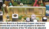
On a Sideband capable radio in this series (Galaxy et cetera...), has a Mirror Board. In the AM/FM only series such as a CX33, it has jumper wires along the top of the JP7-8-9 area near the TX Final(s) and driver. The top longer jumper wires (connected in the center) not the short jumper J40.

CX33 - TP7-8-9 jumpers.jpg


He meant to just measure the voltage from anywhere along these wires reference to board ground, a nearby IF can for instance, should be around 5-6v DC.
 
  • Like
Reactions: JDE
Oh geez...

You have this...
1652650933443.png
Last question, what is the mirror board?
1652650869603.png

You don't have a Mirror board, even though it's a EPT360014 board...

You just measure the voltage from those jumpers (Where the clips for the Mirror Board go) across to ground FOIL BOARD ground (like those tuning cans - they are shielded to FOIL BOARD ground not case)

Oh well, back on vacation - It pays to read the thread fully before I post next time...
 
  • Like
Reactions: NZ8N
Modulation "drops" when the voltages go up - so keep it about 5 to 5.6 volts and see how the mod improves.

Party due to the amount of power that the AM Regulator has to swing and where the radio "pre-sets" the AMC and ALC - so if you took out TR32 (or TR37 by label you just replaced) you will find modulation goes up.

The AM regulator tries to keep it symmetrical - the AMC and ALC are preset to accept input at a given power level - so the higher the carrier power - upsets that setting and forces audio to be weaker - so the radio tries to back it down.

So, what are you to do?

There are several mods to fix that - so I'll let those of the radio crew take that over and you can choose the best (or modifications thereof) of all to apply to the radio.
 
  • Like
Reactions: NZ8N and JDE
Modulation "drops" when the voltages go up - so keep it about 5 to 5.6 volts and see how the mod improves.

Party due to the amount of power that the AM Regulator has to swing and where the radio "pre-sets" the AMC and ALC - so if you took out TR32 (or TR37 by label you just replaced) you will find modulation goes up.

The AM regulator tries to keep it symmetrical - the AMC and ALC are preset to accept input at a given power level - so the higher the carrier power - upsets that setting and forces audio to be weaker - so the radio tries to back it down.

So, what are you to do?

There are several mods to fix that - so I'll let those of the radio crew take that over and you can choose the best (or modifications thereof) of all to apply to the radio.

Shouldn't there be at least some modulation on AM? According to the meter and the Bird43 it's not modulating at all after removing that R240 mod and putting TR32 back.

Also, tried following the below guide to align the TX section and ran in to several issues;

http://73.235.100.209/radios/galaxy/dx33hml/dx33hml_trans_adj.html

RF AMP Chain: adjusting L43 and L44 do nothing according to the Bird.

AM Carrier Power High: Max is 6.5w on bird, so I set it to 6w.

AM Carrier Power Medium: Skipped, only have HI and LO.

AM CarrierPower Low: If I adjust below 2w, I seem to lose RX? It's set to 1w.

RF Meter: Matched to the 1w LO dead key.

I didn't do the AMC HI/LO alignments because I don't have a modulation meter. I do know they had little to no effect on modulation on AM.

Also, that voltage you told me to check came out to 5.92v. I'm not sure where that is adjusted, or what it should be set to.
 
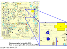
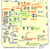
1652661026627.gif

This is for a 33HML (3 position switched Hi-Mid-Low power) but you do get the layouts.

The Voltage reading is important - it determines if you even get 6 watts.

At 5.6 volts - you should be between the 4~5 watts - if you're not getting that then there are issues, but I wanted to stop and ask about your Bird 43 - if you trust this meter - then the fuss is about the Galaxy not showing the meter the modulation?

Ok, Modulation on the 43 Bird, or are you looking at swing?

Then there are more mods we haven't found or uncovered - again, I'll have to defer this to those that started with you on this as I go over the posts with all the mods they did find.

No one seemed to care about the "dual final" - so did this get a IRF520 or does it still use the older Bipolars and what ones are being used?

Sorry can't read those numbers on this end.

Why would it matter - you're having trouble trying to get modulation - and by what I see this SHOULD have the MOSFET mod done to it for just this reason...
1652662100906.png
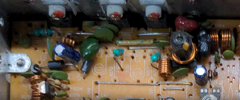
The coupling cap should be a 1500pF or 152 - that cap in there now is quite large so knowing this and below the board on the foil side - there is another cap that straddles this one - looks like to pass as much RF to the next stage (Final section) So to me this is a MOSFET converted radio.

Doesn't explain the "low mod" issue except for that once you remove TR32 limiter - the modulation seems to come back.
  • Again, understand that we are working on a radio once considered stock worked one way and had less components in the TX strip than it uses now.
  • We do not know of the condition of these parts - only that tests by your showed they worked to a point
  • There are still more mods to the radio that unless we can see them - we can only guess at what you should do next.
IF you want my opinion - and not everyone does - but to help you more requires more rework, this may need to involve a shop that you need to trust so they can rework the radio to match the new components more closely.

The crux here is the General Lee used a board that can take in this MOSFET and two finals conversion - but the component list used values for SINGLE Bipolar final.

One aspect here is carrier control - the 14B versus the 14C - when the power levels were changed on the older boards - the AMC had to change its operational window as well - the 14C and 15 versions and above worked AM Power level as a RATIO of used voltage (Carrier) to drive (Modulation), to the level of modulation - so they tried to make the window correct by using FIXED values as long as the AM power the radio inside used - and pre-set - the radio will work in a specific way and predictable.

Someone's been in there and added a few more things but haven't corrected the condition - to tell you exactly what to do from this moment on requires a shop that knows Galaxy chassis like this.

Ok, we now know there are TWO MOSFET and One Driver also should be some type of MOSFET - so the weak modulation then comes from the AM Pass transistor used - located on the side panel side where you found two Transistors that get very warm.

The one at mid-point of the board panel side is the VOLTAGE REGULATOR - you might want to upgrade this or at least look into previous posts about Galaxy Mods to find drop-ins that can work here. The used to use a 2SA473 - but others have used TIP series with some success

The one towards the back - by that long flat chip (Audio Amp) is the AM Regulator - being the one that pushes the modulation into that Jumper and TX strip.

If that has not been upgraded - then at least look at the numbers printed on it so we can find a suitable replacement for it. IT may be your whole problem (in context but see above) .

Some MOSFET mods KEPT the original AM Regulator - and just jumped the Final with 12V to save trouble at the cost of some modulation effect This worked for many a SSB and FM user - but not so much the AM crowd because it needs linearity (volume) in the carrier signal to push the modulation in the envelope.

So some choices have to be made.
 
  • Like
Reactions: NZ8N
The Voltage reading is important - it determines if you even get 6 watts.

At 5.6 volts - you should be between the 4~5 watts - if you're not getting that then there are issues, but I wanted to stop and ask about your Bird 43 - if you trust this meter - then the fuss is about the Galaxy not showing the meter the modulation?

Ok, Modulation on the 43 Bird, or are you looking at swing?

So I'm getting 5.92v, but since I'm still learning I don't really know or understand what this means, how it's adjusted, how it affects the TX circuit, etc.

When you say 4-5watts, do you mean 4-5 watts of swing/modulation?

Compared to other meters I've had, I'd say I trust the Bird43 to be within 1-2w of accurate, and when tested on known good radios it does show modulation/swing when I'm talking in to the mic on AM. The needle barely moves at all with this radio, there's no modulation/swing but I can hear myself on my monitoring radio. The meter in the radio has the same result, just sits still on deadkey and when talking/whistling in to the mic.
Then there are more mods we haven't found or uncovered - again, I'll have to defer this to those that started with you on this as I go over the posts with all the mods they did find.

No one seemed to care about the "dual final" - so did this get a IRF520 or does it still use the older Bipolars and what ones are being used?

Sorry can't read those numbers on this end.

Why would it matter - you're having trouble trying to get modulation - and by what I see this SHOULD have the MOSFET mod done to it for just this reason...

The coupling cap should be a 1500pF or 152 - that cap in there now is quite large so knowing this and below the board on the foil side - there is another cap that straddles this one - looks like to pass as much RF to the next stage (Final section) So to me this is a MOSFET converted radio.

Apart from the straddling caps on the back of the board, the resistor to clean up/lower volume on talkback, haven't been able to ID any other mods.

The driver, pre-final, and final (assuming those are in order from left to right when looking at them) are Mitsubishi C2166, C2312, and C2312.
Ok, we now know there are TWO MOSFET and One Driver also should be some type of MOSFET - so the weak modulation then comes from the AM Pass transistor used - located on the side panel side where you found two Transistors that get very warm.

The one at mid-point of the board panel side is the VOLTAGE REGULATOR - you might want to upgrade this or at least look into previous posts about Galaxy Mods to find drop-ins that can work here. The used to use a 2SA473 - but others have used TIP series with some success

The one towards the back - by that long flat chip (Audio Amp) is the AM Regulator - being the one that pushes the modulation into that Jumper and TX strip.

If that has not been upgraded - then at least look at the numbers printed on it so we can find a suitable replacement for it. IT may be your whole problem (in context but see above) .

If the chassis-mounted transistor closed to the front is the VR, that's an A1869.

If the one closed to the rear panel is the audio amp, it's B754.

Seems my options are either try to track down all the mod changes and revert them, or restore the mod changes to R240/TR32, run it modded, and just get it aligned? It was definitely a splatter box according to my monitoring radio, but sounded OK.
 
The parts to this problem are,,,

One...
Hidden mods - some fixed, but otherwise and now obvious are the other coupling stage from the driver to the "twin Finals" - which to me is too much and should be made equal. I would recommend 390pF To 470pF in a DISC cap - not a Polystyrene or chiclet cap - they are more made for audio passing than RF - but a regular Disc cap of 100V rating at 470pF - you'll need two one to couple the Driver to one Final and split into the other one to go into the other Final.

Secondly -
IF you "revert" back to what it had - then you still have the mess you started with - you can do that but this doesn't help extend the life or enjoyment of the radio then what originally started out with.

As far as the "bird meter" ok, just wanted to know - you ARE LOOKING AT CARRIER POWER - when you set the voltage to 5.6 volts.

I sent you a layout ID posted it earlier - you adjust AM Power to get this right at the jumpers - in AM mode (tx into a dummy load is the best way to test this)

Been trying to find a good quality schematic and some photos from my archives of radios with dual finals - but either way, the caps being used from Driver to Final it is necessary to change them to lower values use two of same type and install so they go to the "base lead" of the two finals - so they branch from one feed point from the driver - then split into the two caps into the Finals.

It is my belief that when you have "low modulation" it is due to the coupling network changes made - you have to lessen the input signal so it can be split equally and applied symmetrically - so the modulation that is being imposed on the carrier - is enough (not too much - it wipes out or "boxcars" the signal while too little carrier the thing swings backwards)
 
Last edited:
Your post with the parts used, the 2SB754 is stock values for the type of radio - so what I posted above - the changing to smaller DISC cap values - might help with this and you may not need to upgrade.

The 2SA1869 is used like a 1.5 to 2A regulator - so it should be enough for MOST radios used stock and even with a limiter clipped - the heat comes from having to drop a lot of power across it when the amps needed to be used are being drawn at 8 volts - that's the rub. if this gets hot at idle use - just listening in - then you have some work to do - try to find the current hogs in the circuits - more than likely it is from older electrolytic caps - instead of being capacitors - are drying out and turning into resistors.

So, I don't see any Echo boards or Frequency Counters and or audio processors sucking all that power - so it may need the tune up but as a correctional means - fix the slider so it doesn't use a lot of power to achieve a lot of slide it can't stay on frequency with, or Mic mods - which I don't see a lot of work done in the area around the Mic amp (that 4558 chip IC) .

So, to me, its age related, and although modded, the mods can be easily undone and redone with proper values - the age seems to be the key player so it will need some TLC until this sucking condition can be fixed.
 
  • Like
Reactions: JDE
just a couple of things to add.

there is a chance your TX section is tuned for maximum deadkey causing the low modulation symptom.

when you start your TX alignment, you start at the center of the band (channel 20) and have your mic gain DOWN.

the first two stages are not modulated so you will be tuning for max deadkey.
L44 and L43 are really broadbanded which is why you aren't noticing any changes when turning them.
they are peaked using AM deadkey.

L42 and L40 will be the next two cans to peak, and again, using only a deadkey.
these two cans will affect the spread of power across the bands, so after you peak them in the center of the band you are mostly using, you need to go to the upper and lower band edges and make sure you have nearly the same power out there that you do in the center of the bands.
Just make small changes to get the power as even as you can across all freqs.

now you are on to L33, and this one needs to be peaked for maximum MODULATED wattage.
so turn your mic gain all the way up, and either speak into the mic or use a 1K tone from a function gen or even your phone and a YT video to modulate the transmitter.

now peak L33 for max modulated wattage.

next you will set your max and minimum deadkeys using VR13 and VR16.
these two controls are somewhat interactive so you'll need to go back and forth to get the limits you want.

just remember to have the external RF power knob all the way up when adjusting the high power, and all the way down when adjusting the low power.
starting with low power you would have the external knob all the way down, mic gain all the way down, and key the mic.

Adjust VR16 for your desired low deadkey. i like 1 watt.
now turn the RF power knob all the way up and set your high deadkey using VR13. I like 6-8 watts for a dual final radio.
now go back to VR16, turn the RF power knob down again, and check it.
your 1 watt will most likely have changed a bit, so re-set it.
now do high power again and you should be good.

next is to set your modulation using VR12 and VR14.

turn your RF power all the way down, mic gain all the way up, and adjust VR12 for max modulation.
does this VR have any effect on modulation?
if not, you have mods you need to remove.

now power all the way up and use VR14 for max modulation.
again, if this VR has no effect, you have mods or problems to take care of.

hope this helps.
LC
 
  • Like
Reactions: JDE and Handy Andy
just a couple of things to add.

there is a chance your TX section is tuned for maximum deadkey causing the low modulation symptom.

when you start your TX alignment, you start at the center of the band (channel 20) and have your mic gain DOWN.

the first two stages are not modulated so you will be tuning for max deadkey.
L44 and L43 are really broadbanded which is why you aren't noticing any changes when turning them.
they are peaked using AM deadkey.

L42 and L40 will be the next two cans to peak, and again, using only a deadkey.
these two cans will affect the spread of power across the bands, so after you peak them in the center of the band you are mostly using, you need to go to the upper and lower band edges and make sure you have nearly the same power out there that you do in the center of the bands.
Just make small changes to get the power as even as you can across all freqs.

now you are on to L33, and this one needs to be peaked for maximum MODULATED wattage.
so turn your mic gain all the way up, and either speak into the mic or use a 1K tone from a function gen or even your phone and a YT video to modulate the transmitter.

now peak L33 for max modulated wattage.

next you will set your max and minimum deadkeys using VR13 and VR16.
these two controls are somewhat interactive so you'll need to go back and forth to get the limits you want.

just remember to have the external RF power knob all the way up when adjusting the high power, and all the way down when adjusting the low power.
starting with low power you would have the external knob all the way down, mic gain all the way down, and key the mic.

Adjust VR16 for your desired low deadkey. i like 1 watt.
now turn the RF power knob all the way up and set your high deadkey using VR13. I like 6-8 watts for a dual final radio.
now go back to VR16, turn the RF power knob down again, and check it.
your 1 watt will most likely have changed a bit, so re-set it.
now do high power again and you should be good.

next is to set your modulation using VR12 and VR14.

turn your RF power all the way down, mic gain all the way up, and adjust VR12 for max modulation.
does this VR have any effect on modulation?
if not, you have mods you need to remove.

now power all the way up and use VR14 for max modulation.
again, if this VR has no effect, you have mods or problems to take care of.

hope this helps.
LC

When you say RF power knob, is that the RF Power High/Low switch? The only RF knob I have is the dual pot for mic gain/rf gain.
 
sorry yes, the RF power switch on the face of the radio.

So many different options with this board i forget which radio has what.
LC
 
  • Like
Reactions: NZ8N
Didn't touch L44, L43, L42, L41.

L33 had little to no effect.

VR13 set to 6w, won't go higher.

VR16 set to 1w.

VR12 does nothing that I can see on the Bird.

VR14 did work, but minimally. Basically I went from 0 swing to maybe 1w swing.

Andy's probably right on the caps he was talking about. There are two sets of straddled caps in that area that probably aren't factory. Problem is hardly any manufacturer offers a parts diagram so I can see whats supposed to be there. Plus there are 999 variations of this board which makes it even more difficult to figure out.
 
Last edited:
I lost audio out in low rf power after the above adjustments. Radio shows mic keyed, is putting out 1w, monitoring radio is picking up the TX, but my audio out is dead. Even have no audio when I enable talkback. PA works. What could this be, based on the symptoms?

Also noticed another interesting symptom that may have been there the entire time...it seems I lose TX power and modulation after the radio warms up. I went back out to the bench after a few hours to see if the no audio out on low issue was still occurring, and noticed hi was putting out like 10w. I had far more adjustment on hi deadkey, and after some testing it dropped back down to 5-6w. I assume once something in the radio heats up, it starts acting up and cutting my power.

That B574 transistor also heats up about 20f more than the other two chips on the side of the chassis. While testing hi deadkey, that chip hit 100f while the other two were in the 80s. Isn't that the audio amp?
 
The AM Regulator that B754 (B574?) - is a simple transistor - the "audio amp" is the long 9 pin package just towards the front panel but by it. Handles RX and Talkback but all the audio you hear on air is done thru that AM Regulator transistor.

IF the Audio amp gets "hot" that usually tells me the radio has drying out or dried out caps - that chip can run warm, but when in TX it is not "on" unless you have talkback enabled - it's purposely muted so might want to look into this too - see if the "Talkback" feature is permanently disabled - you would see the diode that takes TX power and sends it to the Audio chip - D89 - if that has been cut or otherwise messed with solder side too - another mod that has to be undone.

1653184945549.gif
In the CB Tricks archives TR39 (or TR30) uses a jumper wire - just remove that wire and then retest the radio for temperature and also look into purchasing some caps to help refresh the filter and audio passing sections that Audio amp sends power to thru these caps.
 
  • Like
Reactions: JDE

dxChat
Help Users
  • No one is chatting at the moment.
  • dxBot:
    Tucker442 has left the room.
  • @ BJ radionut:
    LIVE 10:00 AM EST :cool:
  • @ Charles Edwards:
    I'm looking for factory settings 1 through 59 for a AT 5555 n2 or AT500 M2 I only wrote down half the values feel like a idiot I need help will be appreciated