• You can now help support WorldwideDX when you shop on Amazon at no additional cost to you! Simply follow this Shop on Amazon link first and a portion of any purchase is sent to WorldwideDX to help with site costs.

Older Connex 3300HP-ZX mod identification?

The AM Regulator that B754 (B574?) - is a simple transistor - the "audio amp" is the long 9 pin package just towards the front panel but by it. Handles RX and Talkback but all the audio you hear on air is done thru that AM Regulator transistor.

IF the Audio amp gets "hot" that usually tells me the radio has drying out or dried out caps - that chip can run warm, but when in TX it is not "on" unless you have talkback enabled - it's purposely muted so might want to look into this too - see if the "Talkback" feature is permanently disabled - you would see the diode that takes TX power and sends it to the Audio chip - D89 - if that has been cut or otherwise messed with solder side too - another mod that has to be undone.

In the CB Tricks archives TR39 (or TR30) uses a jumper wire - just remove that wire and then retest the radio for temperature and also look into purchasing some caps to help refresh the filter and audio passing sections that Audio amp sends power to thru these caps.

The AM Regulator is the hottest of the three, I was mistaken and thought that was the audio amp. Audio amp sat around 80 and didnt move much when TXing, so it sounds like it was working as expected.

I'm going to start replacing the electrolytic caps since I have most of those on hand. I do not have any disc or chiclet caps.

As for the caps you talked about earlier, for the driver/finals, exactly which caps were you talking about?
 
can't remember, have you tested the AM regulator and the TO-220 transistor in front of it?
LC

I have not tested those yet. Still a bit new to this stuff so I don't have a transistor tester, will need to do testing with a DMM.

I just checked the radio this morning; still no modulation, VR16 still seems to hurt my RX when turned fully clockwise to get 1w low deadkey, VR13 still maxes at 6w high deadkey, and I'm still getting no audio out on low keying, just a dead/empty carrier?

So I guess I was mistaken about it working properly when cold, may just be a faulty component.
 
I wanted to touch base on something I saw that needed a little more explanation - whether you needed it or not, at least hear me out...

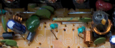
A zoomed shot of the board, referring to the "splitter" I mentioned earlier.

1653237602209.png

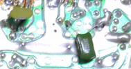
The two green Discs with the blue tips are 470pF NPO (471) so they have done the splitter divider correctly - the problem lies in the big green chiclet and the smaller brother used below in this same area - on the foil side.
1653237723245.png

The smaller green chiclet is 102 - or 1,000pF
and you really should remove this one, so you don't kill your work from too much RF going to one transistor and not enough to the other (starvation).

The Green Olive Disc - the value is unknown but is also an NPO-type so it may be OEM swapped to the bottom of the board when they added in the new part to "dual final" upgrade.

Looks like they just wanted to "copy" one final and duplicate the effort - which is correct, but the problem lies in how much "split" in RF is needed to make both work equally? (Referring to both transistors)

So, if both transistors HFE is correct or nearly equal - the values used in the splitter can be thought of as a simple resistor divider - so they can be used to equalize the amount of RF power sent to the BASES of both - in similar amounts so they can make PEP and AVG power levels equally - more likely than not they kept and used the value of the Olive cap - just kept it since the concept worked.

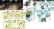
So, you know, the Olive cap is in location C170 - under TR43 - C208 "drawn in" in a latter graphic in this post - is its presumed location - with both C208 and C170 - are part of the "splitter" values used in various production years with transistors that had different output characteristics or HFE during production

So, you need values in there? Possibly - but in small values of capacitance to act as shunts to RF to ground to lessen their presence so the RF doesn't rise up and clip when you modulate heavily into the dual final pair - they are needed to reduce the rise in power to where they clip - but as to how much is specific to the values they used to input (470pF) so I would use 150pF in C170 and C208 spot and see if this works.

So to me, the Olive one needs more attention to solve the riddle of the power (See above) - but in ANY case, the Green 1,000pF Chiclet needs to be removed - you have a jumper in place to one Transistor and it's the one they also use the bottom half of the splitter on - so when you remove the Green Chiclet - check power output - make sure it's producing power - they may have been doing work to make the output less "spiky" for PEP input to an amplifier that doesn't like spikes.

So, you have to verify the work done was correct.


I'll leave this "montage" with you to help you sort out what needs to be used to obtain the dual final but with less capacitance.

The bigger Cap - in C172's spot, by the coil - L37 - should be removed and another DISC cap of 473 (0.047uF) used here to see how power develops.

1653238822069.png
 
About halfway done replacing all the electrolytic caps.

I pulled the AM Regulator and its transistor, need to figure out how to properly test those with a dmm.

Some notes based on your last reply;

-I removed that 2A102J chiclet cap from the foil side. This is not the same style/brand of green chiclets used elsewhere on the board, all those have a different print on them and a little symbol I didn't see on this one. This cap style/brand/printing is common on Cobra 29s from what I can see in my parts radios.

-The blue tipped disc cap on the bottom is 391.

-The top big green chiclet in C172 says 10.4k, and does match at least 3-4 others on the board. So either this is correct or maybe they robbed it from elsewhere on the board?

-C166 looks melted to me, and it's one that has another cap of a similiar style straddling it from the foil side. Is this factory?

-I have no disc caps at all on hand for C172, and the few parts radios I have are Cobra 29s that don't have 473s from what I can find.

-Is there a fairly standard list of disc cap sizes that I can order like I did with the electrolytic caps? It would be nice to have those on hand for jobs like this.

I'm struggling to figure out what's factory and what's not because there are so many variations of this board, and it was used in so many different radios.
 
Some notes based on your last reply;

-I removed that 2A102J chiclet cap from the foil side. This is not the same style/brand of green chiclets used elsewhere on the board, all those have a different print on them and a little symbol I didn't see on this one. This cap style/brand/printing is common on Cobra 29s from what I can see in my parts radios.

-The blue tipped disc cap on the bottom is 391.

-The top big green chiclet in C172 says 10.4k, and does match at least 3-4 others on the board. So either this is correct or maybe they robbed it from elsewhere on the board?

-C166 looks melted to me, and it's one that has another cap of a similiar style straddling it from the foil side. Is this factory?

That Green Chiclet cap on the foil side of the board is not STANDARD for use in RF circuits - it's more for power supply filtering and Pass filtering for Audio amps and Keeping RF out of the power supply feed sections in RF amps but not in itself the best means to pass RF thru it. It's constructed a LOT differently than the parts of the Olive Green Discs are made - so the part itself is more for Audio than RF.

The Blue Tipped cap - 391 means it's value, it's a little TOO large for the purpose and can add a specific problem to "dual final" designs - it will take too much energy away from the two finals to work linearly - but if it were to handle just one - it would do just fine.

But now you'll see 390 divided by two - gets you close to 195pF - so the 150pF value for both C208 and C170 will work well for the splitter values you'll need once you correctly reset the unit closer to OEM then re-do the mod for dual final to make them work in tandem more equally.

Why not 180pF for both? Well, you can, and you might need to - so keep these values in the back of your mind as several extra "Aces" to get past the tricks the radio will try to play on you.

The brown melted cap - is designed to look this way - it is dipped with an epoxy to protect whats inside.

But why two? This is a tweak both radio makers and tech use, the type of cap is a "dipped" mica - more than likely silver mica (A type of plate construction) they are dipped to keep oxidation of the Nobel materials used within it - from spoiling and reduction due to exposure to air - which changes the value from what is stamped on it - to something a lot worse.

You may not need this - so remove it and retest the radio - if it performs worse than with it, then put it back in - more than likely due to the tune-up done before you got it - and is why they needed to add another in.

Heat generated by the RF effects passing thru this type of capacitor - as long as not too much power is applied, they last a lifetime - but too much RF or a wide spectrum of RF not supposed to go thru a stage (open loop oscillation) these - can cause them to heat up and crack - so if you question it - replace it as you can.
 
  • Like
Reactions: JDE
This guy explains the testing very well.


LC

With DMM in diode testing mode I get the following on the AM Regulator(TR51) and its transistor(TR50), both removed from radio;

Voltage from B(+) to E(-).

No reading from B(+) to C(-).

Voltage from C(+) to E(-)

No reading from E(+) to C(-).

No reading from E(+) to B(-), or C(+) to B(-).
 
Just had this Connex 3300HP-ZX hit my bench. This was actually the last radio my father in law used before he stopped driving some years back. He passed away 2 years ago, so this radio has great sentimental value to me and will be going in my pickup. Already cleaned the faceplate, knobs, front chassis area, mic port, 3.5mm jacks, knob pots, and replaced the burnt out bulb in the meter with a white LED.

It does transmit. Low = 2w deadkey, swings 15~. High = 6w deadkey, swings 20~. This is on a Bird43 and 50w slug, no other meter to compare to at the moment, and I've never had this Bird aligned so it may be off a bit. Sounds great on my nearby monitoring radio, a 20~ year old General Lee that is aligned.

It also receives well from that same General Lee, clean and clear for the most part. It has a bit of static crash, and that's standing back from my workbench not touching or bumping the radio at all, volume 25%, RF gain up, AM/High Band D/any channel. Didn't seem to affect the quality of receive, though.

The two transistors on the right side of the chassis(audio amps?) do seem to run warm. Driver and finals get a little warm after TXing for a while, not unexpected, and this was in a 80-90f garage.

I'm still very much learning the ropes here so I'm trying to figure out what mods, if any, have been done to this radio. In the component side photo, top right, to the right of the DC filter cap you'll see two diode/resistor combos(don't have PCB numbers on those yet), doubt those are factory. There have also been some caps replaced on this radio. This thing probably saw a truck stop repair guy once or twice in its life.

Also wouldn't mind some schematics/mod info/etc. One cbtricks mirror site doesn't have anything for this radio(cbtrickz), and the other mirror site has been down for weeks(robco). Pictures attached. Thanks!
one is an audio amp, the other is am regulator
 
Might be at a point where I'm going to have to send this one off to get repaired by a proper shop. Can't seem to figure out what's wrong with it and why I lost audio out on TX, it's a bit more than I can tackle since I'm still learning things.
 
I'm an idiot. Apparently bumped the multiplier switch on my Bird43 peak kit so I've been viewing the wrong readings for weeks. Luckily I haven't burned anything up with that stupid mistake.

Getting TX and audio out on the radio again, going back through the calibration.

Also, worth noting here that my General Lee has the exact same caps in the same places. The 2x chiclets, the disc cap across the final, etc. Even has the same driver, pre-final, and final. Either both radios happened to have the same exact mod done, or that's factory.

I am still getting that weird issue where I seem to be getting full power at first, then after some testing/calibration and things are warming up I lose TX power on hi and low. Example, I'll calibrate RF high to 7w, then after 5-10 minutes I check it again and it's down to 4 and that VR will only adjust it up to maybe 6w now instead of 10+ like normal. What could be causing this issue?
 
I am still getting that weird issue where I seem to be getting full power at first, then after some testing/calibration and things are warming up I lose TX power on hi and low. Example, I'll calibrate RF high to 7w, then after 5-10 minutes I check it again and it's down to 4 and that VR will only adjust it up to maybe 6w now instead of 10+ like normal. What could be causing this issue?

Are the Driver and Final pairs getting warm to the touch when they just sit there no TX?

If so, you have a Diode or bias climb (because of a flakey diode) turning on the parts slowly - until they stay on and pull all the power, they can out of the AM regulator transistor - which could explain the heating up issue

Driver and Finals don't seem to be getting warm unless I'm TXing. AM Regulator gets the warmest when TXing. At idle, everything is cold.
 
At idle, everything is cold.

Good to know...

You'd know something was up when the RF falls flat and the smell (stench) of hot parts is becoming more noticeable. That is the "bias climb" I'm referring to - where the voltage used to keep the stage in Class AB, bias starts applying more voltage - turning the stage more into Class A and they latch on - and stay on until the power is cut off.

To me this seems to be segue-ing to an alignment problem - where more RF out of band is getting amplified as well. The system is not supposed to amplify 2nd harmonics nor even the fundamentals of the Mixer products (less than 2nd (52~54MHz) but still above 28MHz) - but this loss of RF as it warms up signals a leaky cap or the filter used to keep 27MHz but get rid of the rest - failing as temperatures go up - seems to be what this is now showing more of.
 
I'm still in the process of getting all the electrolytic caps replaced. I haven't touched any disc or chiclet caps, since I'm struggling to figure out what values/sizes to order. The cylinder caps are easy so I have a surplus of all the most common sizes.
 

dxChat
Help Users
  • No one is chatting at the moment.
  • dxBot:
    Tucker442 has left the room.
  • @ BJ radionut:
    LIVE 10:00 AM EST :cool:
  • @ Charles Edwards:
    I'm looking for factory settings 1 through 59 for a AT 5555 n2 or AT500 M2 I only wrote down half the values feel like a idiot I need help will be appreciated