Not bad thanks for the info i sent my to a amp builder in the NE he is going to re-do the 40 and 20-meter band with the correct setting and fix the low side input trimmer with a pot in the back of amp so every time the band is switched simple to adjust

You are using an out of date browser. It may not display this or other websites correctly.
You should upgrade or use an alternative browser.
You should upgrade or use an alternative browser.
-
You can now help support WorldwideDX when you shop on Amazon at no additional cost to you! Simply follow this Shop on Amazon link first and a portion of any purchase is sent to WorldwideDX to help with site costs.
-
A Winner has been chosen for the 2026 July 4th Retevis RA89R Giveaway! Click Here to see who won!
Palomar 300A refresh. Assume nothing.
- Thread starter nomadradio
- Start date

NOMAD: If you pay any attention to your Ebay Sales dept. you will note and order from me.
Story begins. I took a 300A in trade years ago for ??
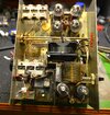
Couple years ago decide it was time to move it forward. Tested tubes / cleaned her up / fired up ...Works all bands 40 thru 10...300 to 400 watts carrier on high drive w/(6 watts drive)...Good to go. Took to XENIA, priced her at $275 as a start...by time to leave was asking $225...took it home placed on shelf...Now 2+ years later, time to move...cleaned the dust and realized this thing had antique caps! OK had some in-house...swap out the 2/450v and 2/25v...caps. Lace up some very ugly wiring.(that old wire is brittle)and closed her up.
Flip the switch...dark...nothing... WTF ...Check fuses ...both blown...OK Dumass!!! what did you F'up swapping out those few HV parts...Looked things over, even to a point of removing the board to check for a solder bridge or stay splatter...nada...OK Dumass wtf is up!
Pictures and more in Part 2
All the Best
Gary/W9FNB
PS: I have surmised this is a VERY late production 300A/White face/Chrome top...After further review not sure what "version" this is...the search for info continues
This has 4/6KD6's finals...2/ 6lf6's drivers
Story begins. I took a 300A in trade years ago for ??
Couple years ago decide it was time to move it forward. Tested tubes / cleaned her up / fired up ...Works all bands 40 thru 10...300 to 400 watts carrier on high drive w/(6 watts drive)...Good to go. Took to XENIA, priced her at $275 as a start...by time to leave was asking $225...took it home placed on shelf...Now 2+ years later, time to move...cleaned the dust and realized this thing had antique caps!
OK had some in-house...swap out the 2/450v and 2/25v...caps. Lace up some very ugly wiring.(that old wire is brittle)and closed her up.Flip the switch...dark...nothing... WTF ...Check fuses ...both blown...OK Dumass!!!
what did you F'up swapping out those few HV parts...Looked things over, even to a point of removing the board to check for a solder bridge or stay splatter...nada...OK Dumass wtf is up!Pictures and more in Part 2
All the Best
Gary/W9FNB
PS: I have surmised this is a VERY late production 300A/White face/Chrome top...After further review not sure what "version" this is...the search for info continues
This has 4/6KD6's finals...2/ 6lf6's drivers
Last edited:
Ah, "both"? It came with one fusholder on the rear of the RF deck. We adopted the habit of putting a 15 Amp fuse in a holder on the power transformer to protect the low-voltage winding. Found that a short on the 12 Volts alone might not trip the AC fuse in time to protect the 12-Volt winding, especially if someone had used a 30-Amp fuse.Check fuses ...both blown
I would start by pulling the tubes and trace for a short to ground on the 12 Volts AC.
73
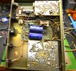
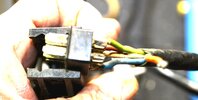
A Few pics. This is after removing the board and went ahead and replaced the old 5406 Diodes w/5408 Diodes...(600v vs 1000v 3 amps) still need to redo some busted connections...report thr later...Last two pics...might serve as part of blown fuses issues...Orange wire...(cold solder joint) lifted itself from pad an was moving or toughing the green wire...First issue to resolve is this NASTY power plug...More Later
Attachments
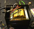
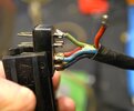
Yes: See pic #I ... Couples to fan motor and power switch. Not sure how many "people" been in this amp...but there is some real "crummy" wiring done. I know that wire is 60 years old, but it was some cheap SH*T back then...now brittle and insulation is thin. Have found B+ wire going to final Plate choke has copper showing through right at the edge of the board...Still finding "stuff"...Beginning to wonder how this worked 2-3 yrs agoIt came with one fuse holder on the rear of the RF deck?
")
Anybody have a "NEW" version schematic...I have older version I am sure.
As I have found there are about 4/5 versions at least...

I have the:
A:/Low voltage PS ... using the Voltage Doubler
B:/ HV Relay mounted on HV board
C:/ Version w/ P&B RE50 series relays...
(Hence placing a order to NOMAD)
Hope I don't need that stuff...and just sell it with amp...or just grit and change it all...
Work in progress.
All the Best
Gary
As I have found there are about 4/5 versions at least...
I have the:
A:/Low voltage PS ... using the Voltage Doubler
B:/ HV Relay mounted on HV board
C:/ Version w/ P&B RE50 series relays...
(Hence placing a order to NOMAD)
Hope I don't need that stuff...and just sell it with amp...or just grit and change it all...
Work in progress.
All the Best
Gary
Last edited:
I finally was able to bring back the Palomar 350z my father bought back in the 1980s last month. But as it was stated in another thread when I asked, it isn't quite worth the investment to try and get it going again as that particular model is riddled with issues that the cost to even try and get the bugs worked out, it is best to use the money somewhere else.
Would buying a 300A be the best Palomar Tube amp to buy? I honestly wouldnt mind a smaller Palomar tube amp even if it uses 2 tubes vs 4 tubes. I am unsure of the condition of the tubes inside the 350z here, but if they checked out ok, I wouldnt mind putting them into a different amp and using what is left of them.
I don't mean to de-rail the thread, but figured I would at least ask the best route to take to make use of the 350z for parts on another tube amp.
Just my thoughtsI finally was able to bring back the Palomar 350z my father bought back in the 1980s last month. But as it was stated in another thread when I asked, it isn't quite worth the investment to try and get it going again as that particular model is riddled with issues that the cost to even try and get the bugs worked out, it is best to use the money somewhere else.
Would buying a 300A be the best Palomar Tube amp to buy? I honestly wouldnt mind a smaller Palomar tube amp even if it uses 2 tubes vs 4 tubes. I am unsure of the condition of the tubes inside the 350z here, but if they checked out ok, I wouldnt mind putting them into a different amp and using what is left of them.
I don't mean to de-rail the thread, but figured I would at least ask the best route to take to make use of the 350z for parts on another tube amp.
If I had to choose, it would be the 300a over the 350z
I have ran both in the past, the 350z is a Hot rod.
In more ways than one, it tended to eat tubes and never made as much power as the 300a.
(Back to your regularly secluded programing)
73
Jeff
Mostly I avoid making negative statements about a particular product. I'll just channel grandma to describe the 350Z. She said "If you can't say anything good, don't say anything. "
Besides that we won't fix one.
73
Besides that we won't fix one.
73

Did you channel MY grandma? I swear I heard her voice saying that as I read it. That, and "children are meant to be seen and not heard."I'll just channel grandma. She said "If you can't say anything good, don't say anything."
73
dxChat
- No one is chatting at the moment.