Hi, I found a Cobra 29 Ltd Classic at a local garage sale. The Ch9/Ch19 Switch of the Cobra 29 Ltd is broken and will not stay in the up position. Can I just solder the 2 - black and yellow wires together?
Thanks,
Thanks,

With this radio being from 2021, the dpdt switch, in the Ch9 switch location, only uses 2 wires. A yellow wire - top pin of switch to the Channel Selector pcb. And a black wire - center pin of switch to pcb ground.i like repurposing them for other mods myself
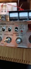
I replaced the Ch9/Ch19 switch with the on/off switch for a RM Italy AD 203 PCB Stinger Board. I also replaced the Delta Tune knob with the dual control knob for a TRB-X3 echo board. And, I ordered a new faceplate which has the replaced controls lettered accordingly.sounds like the perfect easy conversion for something like an echo mod or a diode-switched channel kit oscillator
i like to use the PA switch for stingers or rfx units because it goes from "public address" to "power amp"I replaced the Ch9/Ch19 switch with the on/off switch for a RM Italy AD 203 PCB Stinger Board. I also replaced the Delta Tune knob with the dual control knob for a TRB-X3 echo board. And, I ordered a new faceplate which has the replaced controls lettered accordingly.