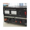
Hi folks, i bought lately a 30 amp variable power supply brand new in his box. This unit was probably sleepling on a sheft since years. The unit was working fine on my radio but the fan was really noisy. So i decided to replace the fan. To change the fan, you must remouve the aluminium tunnel that is cooling the regulators and the bridge. It was manipulated very carefully but two small wires left the circuit and i have no clue where those two wires goes. Can't find the diagram either...help first wire is blue and starts from a heat protection on the tunnel and the second is a yellow that goes to a board connector. I tried to make search with the model, some pictures but nothing came out. The model is a ZURICH DPS-2512M

You are using an out of date browser. It may not display this or other websites correctly.
You should upgrade or use an alternative browser.
You should upgrade or use an alternative browser.
-
You can now help support WorldwideDX when you shop on Amazon at no additional cost to you! Simply follow this Shop on Amazon link first and a portion of any purchase is sent to WorldwideDX to help with site costs.
-
A Winner has been chosen for the 2026 July 4th Retevis RA89R Giveaway! Click Here to see who won!
Problem with my Zurich DPS-2512M Power Supply 30amp
- Thread starter Paslong90
- Start date
![20250909_123944[1].jpg](/data/attachments/71/71688-032a12bc2715bb6d0fa2e18c04c452fb.jpg?hash=IBU1wnPmrO)
![20250909_124005[1].jpg](/data/attachments/71/71689-1d79f43c63b31dc85beaa34f90764fd4.jpg?hash=OxVZnx6t-t)
![20250909_123959[1].jpg](/data/attachments/71/71690-86b8cdebe7000bf48ebebd1879f76572.jpg?hash=aWVQJ5UZQi)
I studied the enlargements of your pictures, and I THINK I know where the wires go
First, I think the blue wire goes here

And the yellow wire goes here.

I'm not 100% certain, but maybe 90%. Pretty sure about the blue wire, yellow maybe. My best shot. Good luck. 73.
J.J. 399
First, I think the blue wire goes here
And the yellow wire goes here.
I'm not 100% certain, but maybe 90%. Pretty sure about the blue wire, yellow maybe. My best shot. Good luck. 73.
J.J. 399
Last edited:
Hi unit_399, thanks for your quick answer. i didn't realized that a part of the line was missing (where you point me the yellow wire. I Had to rebuited this line to weld the yellow wire. That is done.
For the blue, that is another story... when i hook it to the point, i have, on my output, 21/22 volt and i can't change it even with the front knob so no variation
I have a 'working' 2512 and if you are still needing help, I will take the cover off and take some images. I put working in inverted commas as it is still working but is getting poorly after 30 years of hard graft (on for 12+ hrs almost every day for most of those 30 yrs and under a decent load of 6-25Amps). After a spell of transmitting I get the 'hot, melting plastic' smell, plus my one does not have a fan fitted! It's been replaced now, but I'll keep it as an emergency spare. Let me know what you need in the way of images or other info (like you, I couldn't find a circuit diagram). 73, Sean - G4UCJ
This may be a little hindsighted, and I feel your pain, but whenever I open an unfamiliar chassis, I snap lots of pics of the wires and layout before I start manipulating anything. I rarely need the pics but it has saved my butt on the odd occasion. I especially do so if I know it may be awhile before I reassemble, such as waiting on replacement parts.
I have a 'working' 2512 and if you are still needing help, I will take the cover off and take some images. I put working in inverted commas as it is still working but is getting poorly after 30 years of hard graft (on for 12+ hrs almost every day for most of those 30 yrs and under a decent load of 6-25Amps). After a spell of transmitting I get the 'hot, melting plastic' smell, plus my one does not have a fan fitted! It's been replaced now, but I'll keep it as an emergency spare. Let me know what you need in the way of images or other info (like you, I couldn't find a circuit diagram). 73, Sean - G4UCJ
I have a 'working' 2512 and if you are still needing help, I will take the cover off and take some images. I put working in inverted commas as it is still working but is getting poorly after 30 years of hard graft (on for 12+ hrs almost every day for most of those 30 yrs and under a decent load of 6-25Amps). After a spell of transmitting I get the 'hot, melting plastic' smell, plus my one does not have a fan fitted! It's been replaced now, but I'll keep it as an emergency spare. Let me know what you need in the way of images or other info (like you, I couldn't find a circuit diagram). 73, Sean - G4UCJ
I have a 'working' 2512 and if you are still needing help, I will take the cover off and take some images. I put working in inverted commas as it is still working but is getting poorly after 30 years of hard graft (on for 12+ hrs almost every day for most of those 30 yrs and under a decent load of 6-25Amps). After a spell of transmitting I get the 'hot, melting plastic' smell, plus my one does not have a fan fitted! It's been replaced now, but I'll keep it as an emergency spare. Let me know what you need in the way of images or other info (like you, I couldn't find a circuit diagram). 73, Sean - G4UCJ
This user is clearly not very active on here, you might be better off sending him an email via the address that the has on his QRZ page. If you don't have a QRZ account then I can PM you his email address so you can try to contact him there.If you have the chance to take and share few picture of where the blue wire and the yollow goes. it would be awesome
Thanks for the tip... I went and nothing comes out with the name or the callsign. Since he shows only once, i don't expect too much....This user is clearly not very active on here, you might be better off sending him an email via the address that the has on his QRZ page. If you don't have a QRZ account then I can PM you his email address so you can try to contact him there.
Have a look for MFJ-4035. I believe it is the same unit under a different name. Check this out, the cover is off.
Last edited:
I just send him an email on your behalf.Thanks for the tip... I went and nothing comes out with the name or the callsign. Since he shows only once, i don't expect too much....
Best of luck!
I have a Tenma brand 40-Amp supply that looks just like it, but with gray paint. I'll have a look inside and see if there's a blue and yellow wire like this one has. Even if it came from the same factory as yours, no guarantee they used the same wire colors.
73
73
dxChat
- No one is chatting at the moment.