• You can now help support WorldwideDX when you shop on Amazon at no additional cost to you! Simply follow this Shop on Amazon link first and a portion of any purchase is sent to WorldwideDX to help with site costs.
  • Retevis is giving away THREE radios for their 16th Anniversary! Click Here to enter!

radiation patterns of different types of antennas

On 160 i use a 77 feet vertical ( former inverted L of 136 feet) good for ground wave up to 80 miles, though sometimes even further with mixed propagation even midday. ( to the UK)
Low angle for dx till now USA canada, South America EU MIddle east Africa Japan, China Australia and some more in SSB.
For 10, Imax 2K daily direct line of sight 20 to 30 miles to other fixed station ( minimal S9) running 50 to 100 watts SSB.
rest of the world in other propagations, SSB/Digital.
Real ground wave quickly goes down after 3 MHz, the same 77 feet vertical is used with autotuner ( MFJ998) on 80/40/20/17.
There on 80 minimal ground wave not good for local but good for longer distances, for local the OCF FD-4 is used , 40 the same where the vertical has almost non existent ground wave left.
20 and above just low angle work.
Even on 10 some of your RF will bend with the radius of the earth making longer distances possible as to the horizon.
Even happens on 2 meter.
That Imax is at 12 meters up from the ground top at 19 meter, or close to 60 feet above ground above my 3000 feet radial field for 160 meter vertical on salty sea clay.
That same salty sea clay stretches out 20 miles up to the sea.
I bet that helps in any way.
Just my observations after 45 years hamming.
 
  • Like
Reactions: Captain Kilowatt
VU2NSB in India

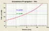
GW-10m.png

S9 @ 7 kM with 100W (4.35 miles)
30 dB. additional path loss
S4 @ 35 kM with 100W (21.75 miles)
18 dB. additional path loss
S1 @ 80 kM with 100W (49.70 miles)

@ this point if we increase radiated power
to 1 kW. to overcome an additional 10 dB.
of path loss that puts the signal in just
beyond the 100 kM. mark or 62.10 miles.

as this relates to R-REC-P.368-7-199203
and R-REC-P.368-8-200503 it's interesting
to note that the worst case scenarios
presented in these documents came in @
115 kM, or 71.40 miles. @ 1kW radiated
power over 3 soil types: very dry ground
and two different versions of fresh water ice.

on the whole, distances over the remaining
8 soil types were far greater than these 3
soil types, ranging from 130 - 180 kM. over
the 5 land soil types and three water types,
in one instance extending to 360 kM. over
a salt water path with average salinity.

https://vu2nsb.com/radio-propagation/ground-wave-propagation/surface-wave-propagation/
 
Last edited:
That is for one station to horizon, if both stations have their antenna up at 60 feet it is different as i said above.
Result
Line of Sight distance (dl)
km 15.2669
Radio horizon - Service range (dr)
km 17.619
X 2 for both station.
So direct line of sight 30.5 KM and service range 35+ Km
In most cases running 100 watt and good 5/8 antenna range is a bit better in most cases, above are the worst case distances.
Line of Sight Calculator | Online Line of Sight Calculator App/Software Converter – CalcTown

Experimenting on 10 i found out the distances are mostly better, certainly if your antenna is free, no obstructions in sight, and then good signal reports are possible over a bit larger distances as calculated.
Maybe my 3000 feet radial field under my antenna's plays a role including good ground.
Anyway, that is what i see here daily on 10 with local qso's.
Not much difference between 10/11 there.
 
Last edited:
"That is for one station to horizon"

The antennas (plural) at both ends are assumed to be at or near ground level.

this is the case in: https://vu2nsb.com/radio-propagation/ground-wave-propagation/surface-wave-propagation/

antennas at ground level and 100W.

also the case in: https://www.itu.int/dms_pubrec/itu-r/rec/p/R-REC-P.368-7-199203-S!!PDF-E.pdf and http://www.itu.int/dms_pubrec/itu-r/rec/p/R-REC-P.368-8-200503-S!!PDF-E.pdf

antennas at ground level and 1kW


"for surface wave (ground wave) propagation-based communication to be viable it is important that both the TX and RX antennas are installed at the ground level or at least within a 1/4 λ from the earth's surface for best results. The surface wave propagation occurs by ensuring that the signal clings to the surface of the earth. Hence, it is not available at heights that are well above the ground." ~ VU2NSB ~
.

"For the sake of this presentation, let me cite below the conditions for which the surface wave propagation graphs are applicable. These attenuation curves have been derived from a simplified but fairly accurate model based on the CCIR ITU-R P_368-7 1992 recommendations (linked to previously) for evaluating ground wave propagation over a smooth surface spherical earth. However, my model has been simplified to account for Sommerfeld-Norton Planar Earth theory since the curvature of the earth can be reasonably approximated due to the relatively short surface distances involved. The model complies to ±3 dB accuracy of the results mapped by the ITU 368-7 document."

"Rather than using a long drawn set of complex equations involving tons of variables, I have derived various intermediate constants applicable to each amateur radio band in question under the specific set of conditions under consideration. This takes into account both the Sommerfeld region that defines the radio horizon AS WELL AS THE DIFFRACTION REGION THAT EXTENDS BEYOND THE RADIO HORIZON."

VU2NSB

thanks for playing.
 
Last edited:
i reacted on Cb/Ham antenna;s used in daily lofe most mounted on an roof.
You now compare apples with oranges.

Only my 77 feet vertical is mounted just above ground on an isolater and fed by the MFJ 998.
 
I'm pretty sure that a 5/8 wave will out-perform a 1/4 or 1/2 wave. Less energy is sent vertically and more of it is set out horizontally
If you are in a valley a 1/4 wave will perform better than a 1/2 or 5/8th wave because of the angle of takeoff of the signal. If you are in a clear area or on a hill & not in a valley the 5/8th wave will outperform the 1/4 or 1/2 wave antennas.
 
Just saying "wrong" without any further supporting material is argumentative and non-productive. For the purposes of the way the original question was asked, I think he got the answers he was looking for.

First, I didn't say everything that was going on with the coil because it wasn't an important part of answering the question asked. But since you want to bring it up, I'll quote the W8JI link (which has been presented here before by me and others):

"The flawed viewpoint is current goes in one end, winds its way around through the physical length of wire in the coil, and after a time delay caused by the copper path length current appears at the other end."

Which is exactly what I said in simpler terms. W8JI goes on to explain what really happens quite well, but it is quite technical. The way I described it works just fine in trying to help someone just starting to understand antenna theory.

Pertaining to helically wound antennas, I don't know where you're getting your material from. Long, skinny coils used in antennas have terrible Q and are terribly inefficient compared to better designs. A helically coiled antenna is just a long skinny coil. Here's another good reference: Topband: How Helically Wound Verticals Really Work


Yeah especially if you're installing this antenna on a corvette or some other fiberglass body. If you need the shield of the coax to provide additional counterpoise on any sheet metal bodied vehicle, you're doing it wrong.


The question was asked from a practical standpoint and answered correctly from a practical standpoint.
If mounting on a Corvette or a Fiberglass Boat you should be using a 1/2 wave because it does not require a ground plane.
 

dxChat
Help Users
  • No one is chatting at the moment.