Much of what I read in your posts, suggests that not just a recap - but perhaps some diode checking too...
Why?
Diodes can have a weak current pass thru them, in doing so, passes along a lot of RF power across them.
Diodes can be used as RF Switches - to turn sections on or off - by passing a live trickle voltage across it to direct RF straight to ground.
Why am I saying this? You encounter a "Howl" sound - tells me there's a feedback issue, or perhaps no feedback - which then indicates several open diodes being used for RF switches in specific modes, are not turning on or off - they're blown open - mixing two signals together - or worse - on all the time, sinking signals that are needed - from getting to the right section to be processed - then filtered out.

In the above, the RF input section uses 1N4148 (PN NOT Schottky) diodes to help protect the input from excessive signals.
 But there is also another type of diode that when it gets power applied - looks like a variable capacitor. Capacitors across the Band Pass Filter section can be used to tune and shunt some signal away, but not by much - so they added a specially made diode - to help take away entire sections of signal and noise to narrow down the amplifiers ability to select and then amplify the signal embedded in all that noise still left - for the IF section to process.
These are Varactors - they act like tunable filters arranged like they are above as a tunable trap - apply a small voltage and the diode then turns into a capacitor - allowing RF to be SHUNTED across it - to varying degrees of power dissipation - like the RF switch the typical PN diode is used for in other sections.
But in this application - the Varactor changes the appearance of bandwidth by tuneability for the signals going thru this section. IT acts like a broad banded Band-Pass Filter (which this is) but has variable attenuation by apply a voltage to it on top of the ability to reduce ripple effects from the noise arriving thru the signals you're trying to tune for. The section remains LIVE having power passing thru it, to wash away signals not able to be fully passed thru this filter section - like running water to rinse away debris in a sink, same concept can be applied here to remove other out of band noise that would otherwise drown out the ability of this section even discern the correct section of bandwidth.
Now, the last one gets' a little bizarre to talk about but is used to effectively not just rinse the sink but wash out everything so it can allow signals from other sections to be processed thru a section - they ISOLATE one sections signals from interfering with another section so this particular section can process the same information from other modes, so it uses SHARED input and output lines.

The above example is for RF switches guiding signals across them, to either drown out the output (stop producing) or allow signal to pass across (like D8)
So, you may have to track down ALL those diodes and make sure they are functional - checked both ways - should only work one way - type of check - any opens or show good both ways may need to be replaced.
Why?
Diodes can have a weak current pass thru them, in doing so, passes along a lot of RF power across them.
Diodes can be used as RF Switches - to turn sections on or off - by passing a live trickle voltage across it to direct RF straight to ground.
Why am I saying this? You encounter a "Howl" sound - tells me there's a feedback issue, or perhaps no feedback - which then indicates several open diodes being used for RF switches in specific modes, are not turning on or off - they're blown open - mixing two signals together - or worse - on all the time, sinking signals that are needed - from getting to the right section to be processed - then filtered out.
In the above, the RF input section uses 1N4148 (PN NOT Schottky) diodes to help protect the input from excessive signals.
These are Varactors - they act like tunable filters arranged like they are above as a tunable trap - apply a small voltage and the diode then turns into a capacitor - allowing RF to be SHUNTED across it - to varying degrees of power dissipation - like the RF switch the typical PN diode is used for in other sections.
But in this application - the Varactor changes the appearance of bandwidth by tuneability for the signals going thru this section. IT acts like a broad banded Band-Pass Filter (which this is) but has variable attenuation by apply a voltage to it on top of the ability to reduce ripple effects from the noise arriving thru the signals you're trying to tune for. The section remains LIVE having power passing thru it, to wash away signals not able to be fully passed thru this filter section - like running water to rinse away debris in a sink, same concept can be applied here to remove other out of band noise that would otherwise drown out the ability of this section even discern the correct section of bandwidth.
Now, the last one gets' a little bizarre to talk about but is used to effectively not just rinse the sink but wash out everything so it can allow signals from other sections to be processed thru a section - they ISOLATE one sections signals from interfering with another section so this particular section can process the same information from other modes, so it uses SHARED input and output lines.
So, you may have to track down ALL those diodes and make sure they are functional - checked both ways - should only work one way - type of check - any opens or show good both ways may need to be replaced.

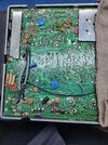
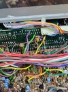
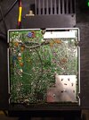
 ) BOARDS that can have a strong light shined thru up from the foil side to illuminate the traces like a mask, so help guide you to finding the right spot to do your test.