
I have read through the very good threads many times about the alignment of bias of the RT1 (IRFZ24NPBF) MOSFET's on the Ranger RCI-69 base as well as the alignment of the MOSFET's on the Anytone 6666.
Two questions:
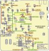
1. When I look at the schematics for the RCI-69VHP (EPT690012D) there is a trimmer pot labeled VR15 but it is not mentioned at all in the alignment procedures. The center pin of the VR15 trimpot goes (via a resistor R271 and a diode D105) all the way up to connector J3 and the pin labelled MM. However, according to the schematics there is nothing connected to pin MM on connector J3. Other pins on J3 (GN, MT and MS) are connected to the S/RF & SWR-meter.
2. There is a test point labelled TP9 (near Q52) on the schematics but the alignment procedures does not mention anything at all what this test point is used for?
I have attached the schematics in PDF-format here and a JPG-picture of the alignment locations.
(I could not find a files section where to upload files?)
Two questions:
1. When I look at the schematics for the RCI-69VHP (EPT690012D) there is a trimmer pot labeled VR15 but it is not mentioned at all in the alignment procedures. The center pin of the VR15 trimpot goes (via a resistor R271 and a diode D105) all the way up to connector J3 and the pin labelled MM. However, according to the schematics there is nothing connected to pin MM on connector J3. Other pins on J3 (GN, MT and MS) are connected to the S/RF & SWR-meter.
2. There is a test point labelled TP9 (near Q52) on the schematics but the alignment procedures does not mention anything at all what this test point is used for?
I have attached the schematics in PDF-format here and a JPG-picture of the alignment locations.
(I could not find a files section where to upload files?)
Attachments
Last edited:

