Working on an older 2950, orange face. Radio turns on, transmits, hears static. However there is exactly, . 277v at J13, L17 does not move the voltage at all, therefore the 10.250mhz reference oscillator is not working. All voltage regulators seem to be working, I've checked for cold solder joints. Any known areas I should check as to where the VCO gets its voltage from. VCO should be set to 2 volts. Thank you for your help, trying to save this one.

You are using an out of date browser. It may not display this or other websites correctly.
You should upgrade or use an alternative browser.
You should upgrade or use an alternative browser.
-
You can now help support WorldwideDX when you shop on Amazon at no additional cost to you! Simply follow this Shop on Amazon link first and a portion of any purchase is sent to WorldwideDX to help with site costs.
-
A Winner has been chosen for the 2026 July 4th Retevis RA89R Giveaway! Click Here to see who won!
RCI 2950, zero VCO voltage
- Thread starter SmoothRadio912
- Start date
I've seen this with bad / shorted caps making the CPU unable to boot - the Voltage may be ok, but the power going into the CPU - Battery ok? If it's flat, it may not "load"
I've seen this with bad / shorted caps making the CPU unable to boot - the Voltage may be ok, but the power going into the CPU - Battery ok? If it's flat, it may not "load"
This model does not have a battery on the CPU board. However I do have a spare working CPU board that I can try. Interesting though all functions work and even transmits power... Just obviously not on said frequency. Worth a shot though.
If this one uses the "programmable PLL" it does a loopback test - so if it's stuck, you did check the Main PCB voltages right? The CPU looks to the main PCB for part of the "Voltage +5 so you can see if the main PCB is sending - you say it is but the CPU also has it's own voltage regulators too.
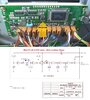
Rick Jacksons CPU schematic has an error in it - the 5V line is not drawn right. But the 5 volts from the main PCB powers up the CPU - the best way I can say this; it's to check is to make sure the tiny little microcode controller is still working - that needs 5V to send data to the CPU for even to load - if the 5V or the Microcode controller is corrupt, the CPU can't boot for it cannot load the code for it to init. Check that chips Pin2 - needs to be 5V feed.
Rick Jacksons CPU schematic has an error in it - the 5V line is not drawn right. But the 5 volts from the main PCB powers up the CPU - the best way I can say this; it's to check is to make sure the tiny little microcode controller is still working - that needs 5V to send data to the CPU for even to load - if the 5V or the Microcode controller is corrupt, the CPU can't boot for it cannot load the code for it to init. Check that chips Pin2 - needs to be 5V feed.
If this one uses the "programmable PLL" it does a loopback test - so if it's stuck, you did check the Main PCB voltages right? The CPU looks to the main PCB for part of the "Voltage +5 so you can see if the main PCB is sending - you say it is but the CPU also has it's own voltage regulators too.
Rick Jacksons CPU schematic has an error in it - the 5V line is not drawn right. But the 5 volts from the main PCB powers up the CPU - the best way I can say this; it's to check is to make sure the tiny little microcode controller is still working - that needs 5V to send data to the CPU for even to load - if the 5V or the Microcode controller is corrupt, the CPU can't boot for it cannot load the code for it to init. Check that chips Pin2 - needs to be 5V feed.
Well I swapped CPU boards with a known good one and same problem.
Also to note, I do have and can adjust the voltage at ic7 pin3, which should be 1.2v.
Courtesy of Buttfuzz:
MODEL: RANGER RCI-2950
PROBLEM: Unit fails to operate on initial turn on. Turning the radio off then back on causes the radio to operate.
REMEDY: This problem is usually caused by the V.C.O. being out of lock. In order to prevent future occurrences, it will be necessary to change C107 to a 100pf NPO disk capacitor. Once this capacitor has been replaced you will need to readjust the V.C.O. voltage. Locate J13 and connect a DC volt meter between it and ground. Set the radio to 28.0 MHz and then adjust L17 for a 1.9 volt reading on the DC volt meter.

Courtesy of Buttfuzz:
MODEL: RANGER RCI-2950
PROBLEM: Unit fails to operate on initial turn on. Turning the radio off then back on causes the radio to operate.
REMEDY: This problem is usually caused by the V.C.O. being out of lock. In order to prevent future occurrences, it will be necessary to change C107 to a 100pf NPO disk capacitor. Once this capacitor has been replaced you will need to readjust the V.C.O. voltage. Locate J13 and connect a DC volt meter between it and ground. Set the radio to 28.0 MHz and then adjust L17 for a 1.9 volt reading on the DC volt meter.
Thank you, I tried this already and no fix. I wonder if L17 is bad because it does not change voltage at all.
Sounds like you found a problemThank you, I tried this already and no fix. I wonder if L17 is bad because it does not change voltage at all.
")
Sounds like you found a problem
I'm not convinced that this is the problem, if no voltage is getting to the area, there will be nothing to adjust.
Are you getting 5V form main PCB to the CPU? It's a loopback ok - one 5V regulator yes (on the CPU card), but there is one it needs from the Main PCB - that has to be power-good condition too - to continue the boot for the CPU - if it doesn't see it - it may be in "self test" mode awaiting to be installed into the Radio .
There is a "one shot" initial condition trigger the CPU board does to itself as if it was a "Wake up"
The Rick Jackson schematic show this "pulse" as a simple charge change to a cap from the 5V line - this change of charge on the cap causes the pulse init - if the cap is shot, or just plain leaky - the cap won't trigger the init routine.
It's why I asked you if you even had a voltage on the Microcode controller (U606) It's pin 2 needs to 5V - for if the Cap works , but the code is corrupt, at least you have an answer...
Connector 611 goes to the Pin 29 of the MAIN CPU - is that ok? It uses the 5V...part of the "E-key" it a simple "tone oscillator" that goes to Pin 29 - but it can use it as a "clock" too - Logic level output (That "beep" error reflects this...)
Else all I can suggest in to look for JP1 and JP2 to see if they can help you "Reset" a corrupt memory issue in the CPU...
OR ... that may be what the prior owner did - corrupted the memory causing the Microcode to be unable to load.
Attachments
Are you getting 5V form main PCB to the CPU? It's a loopback ok - one 5V regulator yes (on the CPU card), but there is one it needs from the Main PCB - that has to be power-good condition too - to continue the boot for the CPU - if it doesn't see it - it may be in "self test" mode awaiting to be installed into the Radio .
There is a "one shot" initial condition trigger the CPU board does to itself as if it was a "Wake up"
The Rick Jackson schematic show this "pulse" as a simple charge change to a cap from the 5V line - this change of charge on the cap causes the pulse init - if the cap is shot, or just plain leaky - the cap won't trigger the init routine.
It's why I asked you if you even had a voltage on the Microcode controller (U606) It's pin 2 needs to 5V - for if the Cap works , but the code is corrupt, at least you have an answer...
Connector 611 goes to the Pin 29 of the MAIN CPU - is that ok? It uses the 5V...part of the "E-key" it a simple "tone oscillator" that goes to Pin 29 - but it can use it as a "clock" too - Logic level output (That "beep" error reflects this...)
Else all I can suggest in to look for JP1 and JP2 to see if they can help you "Reset" a corrupt memory issue in the CPU...
OR ... that may be what the prior owner did - corrupted the memory causing the Microcode to be unable to load.
I will check when I get home, exactly where would I check for the 5v off the main board to the CPU?
C606 on CPU side, J119 if it's labeled as such...
Just make sure the Header is in correctly...Gnd if reversed - goes to the 5V pin, but it won't hurt much unless they tried to defeat something - I'm working with you on unknown condition of the main PCB as well as the CPU...

The 5V pin is PURPOSELY capped to remove the 5.V but if 5V existed on the board, the system then looks at the Mic connector condition (TX/RX thru PTT) - it may then attempt to load - or - reload Microcode. (Because the CPU is empty - ready to accept the code.
It is more of a major concern if the PLL on the main PCB has crossed wires, then the reversal may not have done too much damage - but if the CLOCK and Data inputs are reversed, this part of that "loop" fails, the system thinks there's no PLL connected or the PLL isn't working.
Now I understand why they capped off that 5V - the INIT was to "program" the CPU and force the Microcode to load
Just make sure the Header is in correctly...Gnd if reversed - goes to the 5V pin, but it won't hurt much unless they tried to defeat something - I'm working with you on unknown condition of the main PCB as well as the CPU...
The 5V pin is PURPOSELY capped to remove the 5.V but if 5V existed on the board, the system then looks at the Mic connector condition (TX/RX thru PTT) - it may then attempt to load - or - reload Microcode. (Because the CPU is empty - ready to accept the code.
It is more of a major concern if the PLL on the main PCB has crossed wires, then the reversal may not have done too much damage - but if the CLOCK and Data inputs are reversed, this part of that "loop" fails, the system thinks there's no PLL connected or the PLL isn't working.
Now I understand why they capped off that 5V - the INIT was to "program" the CPU and force the Microcode to load
C606 on CPU side, J119 if it's labeled as such...
Just make sure the Header is in correctly...Gnd if reversed - goes to the 5V pin, but it won't hurt much unless they tried to defeat something - I'm working with you on unknown condition of the main PCB as well as the CPU...
The 5V pin is PURPOSELY capped to remove the 5.V but if 5V existed on the board, the system then looks at the Mic connector condition (TX/RX thru PTT) - it may then attempt to load - or - reload Microcode. (Because the CPU is empty - ready to accept the code.
It is more of a major concern if the PLL on the main PCB has crossed wires, then the reversal may not have done too much damage - but if the CLOCK and Data inputs are reversed, this part of that "loop" fails, the system thinks there's no PLL connected or the PLL isn't working.
Now I understand why they capped off that 5V - the INIT was to "program" the CPU and force the Microcode to load
Thank you! I will check later on, the radio is in good shape, not all hacked up at all, was working then just quit. It does transmit/receive, but on 20mhz or somewhere around there.
Yikes...20MHz - sigh, ok, this does not sound good.
The Main PCB may be more of your problem than the CPU /Display - so you know.
This is similar to the "HR2510" Chip failure - the problem isn't the "chip" it's the PLL03A programming failure - once the main ROM in the (Big) chip is corrupted, it's done - looks pretty but it's motors shot...PLL can't do much when it doesn't know where to go or what to do...
In your case, I hope it's just a Main PCB board failure like the 5V regulator the PLL needs - because of issues around the older TTL and some CMOS devices of yesteryear, if they get power from pins and the device isn't fully powered up - the logic section blows up - acts like reverse polarity power hookups.
dxChat
- No one is chatting at the moment.