• You can now help support WorldwideDX when you shop on Amazon at no additional cost to you! Simply follow this Shop on Amazon link first and a portion of any purchase is sent to WorldwideDX to help with site costs.

Re-capping Cobra 2000 Frequency counter. Tips or tricks?

ShakyMcQuiver

Active Member
Apr 11, 2018
69
57
28
I finished re-capping the main board and now I'm moving on to the frequency counter.
Its board is double sided and can apparently be a challenge to R&R the caps unless you have more than your basic solder removal tool. All I have for solder removal is your basic plunger-type, solder wick and an old Radio Shack bulb-type. I'm not sure if they are going to do the job. I haven't messed around with dual soldered components very much and even when I did, it was not easy or pretty.

The main board on my 2000 was quite fragile when I did the caps and some of the board traces did lift on me, but I was able to repair them. Obviously I don't want that to happen in the Freq. counter module. My counter seems to work fine and it doesn't look like anyone has screwed around inside of it. I've also read about a few pars to replace to make the module more reliable. I may do them while I'm in there.

Any tips from you pros ? Oh and do you really need to replace all the tantalum's? I've read arguments both ways. Some do and some don't. Most of the caps on my main board were out of tolerance (a few were WAY out) so replacing the electrolytics in the freq. module is a no-brainer. I don't know about the tantalum's though.
 

from my experience, it comes down to the proper head range I've changed a few components on the freq counter with no issues patience don't have 5 cups of coffee before starting the job i learn the hard way LOL
 
Tantalums?

Depends upon the environment it was mostly used in.

IF you know of the conditions the radio was put in - then you have to make the call.

Tantalums normally (loose term) don't fail unless their material and dip they used to seal that material - fail. Else voltage and current applied thru them can also cause a "vent" or migration/mitigation across the plates thru the material but the FREQ counter would not work had that happened already.

But if you did not have issues with them on the main PCB, then you should be ok to continue using the OEM ones as long as you're not finding corrosion or oxidation on their leg leads.

Just reheat/reflow solder as possible to verify the integrity of the board.

Tantalums and the choices engineers made to use these in specific spots were from "response" and tolerance to signals and filtering - so to try and find similar material and construct - it might be harder to find working values to accommodate the older tantalum material to make it work by replacing the old that they used back then.

There's an interesting history about Tantalum and how wars and supply chain issues arise from the demand of this product.

1663515786688.png

You may be stuck having to use these older parts and cross your fingers as they continue to work for you.

These boards tend to show oxides when they get taken apart, so the reassembly will have to be a thorough cleaning to avoid noisy ground loop and provide good shielding - back to OEM "clean and prep" as much as possible - at least when it comes to the bolt holes and foil shielding.
 
Thanks again for the replies and technical explanation.

I don't know the full history of this radio. I bought it used several years ago and it's been sitting in my closet until now.

I bought the radio here in southern Oregon so I can only assume that's where it has spent most of its life. There's no rust or corrosion of that nature so I doubt it has been in any humid areas like the coast. You can always tell when a radio has been in those conditions... white crap all over, rust, etc. My radio has none of that.

I've been cleaning the board as I go. Lots of flux everywhere as expected. The traces are fragile and can lift pretty easy, thus why I'm a little nervous about the freq. module. The board in there looks great though. Much better condition (I think) than the main board.

Since it's working, I think I'll err on the side of caution and leave the tantalum's alone until something goes haywire. There are only a few electrolytics so I think I'm safe to R&R those. Based on the other elecro's being out of whack - I'm guessing so are the ones inside of the module.

Thanks!

PS: What do you recommend for cleaning the boards? I've been using a can of electronic spray stuff and a soft plastic brush. It works... eventually. Just wondering if there are better cleaners or techniques? And do you re-seal the board with anything? Since the traces are already fragile... is there anything you can do to shore it up?

Wish I could reproduce these boards. Probably not cost effective, but wouldn't it be nice to have a brand new Cobra 2000/148 mainboard built exactly like they were in the beginning? Heck who knows. Maybe it will happen someday. We already have 3D printers. It won't be long until we have replicators like Star Trek! Just tell the computer to scan your board and make you a new one! :)
I just thought i would throw this out there for anyone who is thinking about recapping a cobra2000 or any other radio, I had never attempted to do a recap before but i have used a manual solder sucker and also wick and found that i had more then a few traces lift. I also knew that i needed to recap my 2000 and was not going to pay to have it done. So i bought a electric solder sucking gun and what a great buy it was! I did the recap of the radio with ease! I then did the freq counter with ease let me tell anyone who wants to do a recap for $39 dollars it makes the job EASY. Not sure if i should post the item here but found it on Amazon and have now done 4 radios plus many repairs with it,
 
  • Like
Reactions: ShakyMcQuiver
I was confirming which electrolytics I need for the freq. counter and ran across something odd...

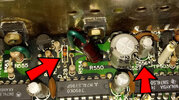
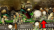
Capacitor #556 (C556) is NOT listed on the SAMS or schematic I have - or at least I haven't found it yet (I'm looking for other schematics). It appears to be a 1µF 50V.

The board number on my freq. counter is: PC-370AB/3.

I've read that there have been a few revisions on the module and I'm wondering if mine is a newer one or maybe it was replaced before I bought the radio? I also can't tell if D528 (5.6 Zener) has been upgraded to the 1 watt. I can't read the numbers on it. They are cheap so I'll replace it anyway to make sure.

At first <quick> glance it doesn't look like any fingers have been inside the module, but upon a closer look I'm not so sure. Unless the factory made a huge mess with the heat grease, then someone has been in there. Also, the two smaller transistors look like they barely have any grease on them.

I was hoping I wouldn't have to mess with the transistors or removing the board but it's looking like I might have to.

C556 and transistors.JPG
freq. counter PC370ab3.JPG
 

Attachments

  • freq. counter C556 .jpg
    freq. counter C556 .jpg
    566.8 KB · Views: 2
My service manual does not show it, but i know mine did have one and i replaced it. Also if you have not watched this video take a look and you will see his also has the 556 cap on his. Good luck!
 
My service manual does not show it, but i know mine did have one and i replaced it. Also if you have not watched this video take a look and you will see his also has the 556 cap on his. Good luck!

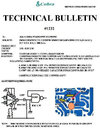
There is also a tech bulletin 1232 you should do to improve the freq counter.
 

Attachments

  • 3998-cobra-2000-counter-fix.jpg
    3998-cobra-2000-counter-fix.jpg
    225.3 KB · Views: 16
There is also a tech bulletin 1232 you should do to improve the freq counter.
Thanks JT.... I did watch the video and I'm aware of the tech bulletin. That's what prompted me to take one more look at things before I dug into it.

I needed to get some parts from Mouser for an upcoming 148 project and wanted to make sure I had everything. Good thing I looked at my module as that one cap wasn't listed. I ran into a similar issue when doing the main board. One of the ceramic puffers was replaced with an electrolytic. Definitely something the factory did. Who knows why.
 
There is also a tech bulletin 1232 you should do to improve the freq counter.
I'm assuming the TSB is referring to a standard-issue ceramic puffer for C557? The TSB is several years old so I'm wondering if there is anything better I should consider. Something high tolerance, etc. It's in the freq. counter after all.

I also looked for Dynascan # 020-204-9-017, but I can't find a cross reference anywhere for the old Dynascan parts.

Too bad there wasn't an updated parts list for the Cobra 2000 re-cap job that shows exactly what type of cap to use. There are so many different types these days.

Searching for parts is very time consuming and I don't necessarily trust a plug-n-pray kit from Fleabay.
 

dxChat
Help Users
  • No one is chatting at the moment.
  • dxBot:
    Tucker442 has left the room.
  • @ BJ radionut:
    LIVE 10:00 AM EST :cool:
  • @ Charles Edwards:
    I'm looking for factory settings 1 through 59 for a AT 5555 n2 or AT500 M2 I only wrote down half the values feel like a idiot I need help will be appreciated