• You can now help support WorldwideDX when you shop on Amazon at no additional cost to you! Simply follow this Shop on Amazon link first and a portion of any purchase is sent to WorldwideDX to help with site costs.

RFI problems with antron 99

Robb, I don't hear the same complaints about the Imax as I do the A99, so there may be a difference if I'm right that the problem could be inside with the antenna's matching device.

If WD was talking about an Imax, that would be different in my mind, and I might have just past on by, and not mentioned the issues that I've experienced with some A99 myself.

I have heard other operators make similar claims about their good results, like you, using their Imax.

I built my own 5/8 wave out of aluminum,works well...this is the precise reason also,no matter what I did to my antron it gave me RFI problems around the house...Sold it to my buddy and he is using it at his hunting camp...I tried radials, grounding,I even took it apart and checked for any loose connections,no help...
 
I had similar issues with my A99, as well as CRAZY SWRs. I was never able to get the RFI completely taken care of but It was reduced quite a bit.

Here are the things I did;

1.) isolated the antenna from the mast.
2.) homemade ground radials
3.) 5 turn mini8 choke at the feed point.

These things did help out.
 
How do you check an RF choke into a dummy load?
- 'Doc

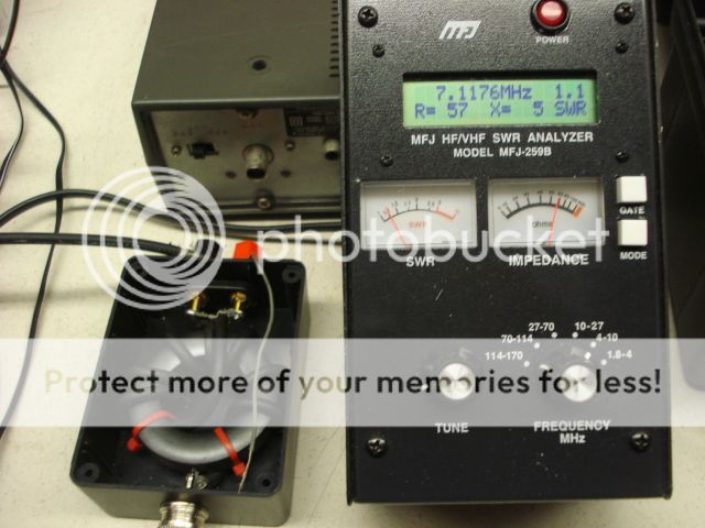
Use a SGC 230 antenna analyser or similar reading SWR. Short out the ground on one the feed side of the choke to the center "hot" on the antenna side. Measure the SWR. Basically:

(Courtesy of Steve Hunt, G3TXQ)

Choking impedance = 100 Ohms, SWR = 1.5:1
Choking impedance = 250 Ohms, SWR = 1.2:1
Choking impedance = 500 Ohms, SWR = 1.1:1
Choking impedance = 1k Ohms, SWR = 1.05:1
Choking impedance = 2k Ohms, SWR = 1.02:1

If you are using an air cooled dummy load built into a large metal box such as one that is part of a MFJ tuner, your readings could be skewed by capacitive coupling to ground. Best to use two 100 Ohm non-inductive resistors in parallel across the load or an oil cooled dummy load.
DSC01830.jpg
 
M0GVZ,
I see how your testing is set up. But please explain to me how you arrived at the choking impedance at the corresponding SWR's.

EG;
Choking impedance = 100 Ohms, SWR = 1.5:1
Choking impedance = 250 Ohms, SWR = 1.2:1
Choking impedance = 500 Ohms, SWR = 1.1:1
Choking impedance = 1k Ohms, SWR = 1.05:1
Choking impedance = 2k Ohms, SWR = 1.02:1

I'm having a problem seeing/understanding how you did that.
- 'Doc
 
That thing at the base of most (if not all) 5/8 wave antennas isn't a choke at all, it's an impedance matching circuit. The input to a 5/8 wave antenna isn't close to 50 ohms so some type/method of impedance matching is always required.
- 'Doc
 
I had similar issues with my A99, as well as CRAZY SWRs. I was never able to get the RFI completely taken care of but It was reduced quite a bit.

Here are the things I did;

1.) isolated the antenna from the mast.
2.) homemade ground radials
3.) 5 turn mini8 choke at the feed point.

These things did help out.

Mr_FX, can you describe a little better the difference you saw? I hear guys talk about differences all the time, but they're seldom specific as to the degree of the difference. Personaly I've added a choke that seemed to work fine one day, and a day later it didn't seem to work at all.
 
Last edited:
M0GVZ,
I see how your testing is set up. But please explain to me how you arrived at the choking impedance at the corresponding SWR's.

EG;
Choking impedance = 100 Ohms, SWR = 1.5:1
Choking impedance = 250 Ohms, SWR = 1.2:1
Choking impedance = 500 Ohms, SWR = 1.1:1
Choking impedance = 1k Ohms, SWR = 1.05:1
Choking impedance = 2k Ohms, SWR = 1.02:1

I'm having a problem seeing/understanding how you did that.
- 'Doc

Got it from a discussion with Steve Hunt G3TXQ on baluns on another forum - the guy who is often quoted on this website when it comes to baluns, chokes etc. He provided the figures.

Basically if you short out to ground the hot side of the floating load (floating in respect to ground) it puts the common mode choking impedance in parallel with the 50 Ohm load. This will alter the SWR detected by the analyser. The higher the choking impedance (good) , the less it alters the SWR. The lower the choking impedance (not good) the more it alters the SWR.
 
I have seen this and solved it many times. While every situation is different, usually the problem has to do with common mode currents along the feedline more than anything else. You can ground everything till you are blue in the face, and also add ground radials which on this type of antenna (not a ground plane) will probably not do a whole lot.

Personally, I would change to 9913 coax, so it is shielded well, and then take 6 turns of it right at the bottom of the antenna feed point and make a small choke reducing common mode currents. You could always buy a common mode filter, but at that point, you would probably be better off with a new antenna system.
 

dxChat
Help Users
  • No one is chatting at the moment.