For starters, learn your scope and be careful what you probe. Depending on the scope type, if you accidentally probe the wrong thing, you can fry the input. Digital USB scopes are typically limited by voltage, whereas many benchtop oscopes have a maximum current limit. Understand the limits of your scope and the signal levels of what you poke at before going nuts with it. There are also grounding considerations because you dont want to accidentally connect your probe ground to something hot (with respect to your scope ground) as all that current must go through your scope ~ poof.
In fact, I'd check out a few videos on "how to not blow up your scope" if you are a first time scope owner.
Assuming all that is good, the next concern is the probe capacitance. You will be measuring some high impedance RF points along the way, and even with a 10x probe, you can still load down circuits to the point their values change or they entirely stop working (the galaxy DX2547 sideband section is a great example). An active RF probe would be the thing to have there as it will not load down the circuit.
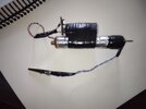
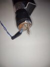
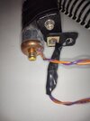
I built this one in a copper pipe based on
this design [link here]. I was going to solder a short ground pin like they did in the article, but I got lazy and used a longer one with a clip (because Im not using it at VHF). It actually works great without even attaching the ground to anything. I get just as stable frequency readings either way. My hand (with it in a metal tube) must offer enough ground (definitely more capacitance than the input) and sufficient noise shielding. I am tempted to cut the ground lead off it.