The 678 sounds like the issue I had with that 621. The 36MHz oscillator went dead, and that threw the PLL out of lock and drove the VCO to its limit (around 38.6MHz if I remember correctly), and with the PLL out of lock, the 10.695 oscillator is dead, so instead of a 37MHz-10MHz=27MHz output, I ended up having 38.6MHz coming out of it. Getting the 36MHz oscillator running fixed that.
If the 641 has the correct frequencies coming out of those test points, its not the PLL unit.
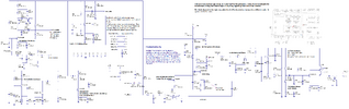
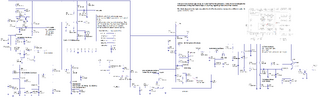
Edit: I would slow down with blindly replacing transistors simply because you can. Many times, component values are specifically chosen based on the characteristics of the part (which can change from batch to batch for the same # part). For example, crystal oscillators usually run around 1mA of collector current. Take a look at my PLL schematic. The lower left section is the 36MHz oscillator that I had trouble with. When I took a voltage measurement across R62 (the 1kΩ collector resistor), I had only a small fraction of a volt there. With 1mA going through a 1kΩ resistor, there should be 1v across it. There wasn't. Thats when the transistor came out and the low gain hinted at a failing transistor or bias problem. In my case, the transistor was making no unexpected noise, so a little more bias current made it work. Now, did the previous owner put the wrong value base resistor in there or was the transistor actuially failing? It arrived broke, and screwdrivered, so I don't know.. What I do know is that the oscillator is now running at 1mA and the new (old) crystal should have a chance to last a while. My point is that if someone goes in there and swaps out that 46 Hfe part with one having a Hfe of 360, the crystal may not be too happy about that.