Well Instead of buying an amplifier like I originally was. I would like to build one instead.
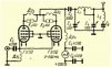
I have this schematic, but would like some input on what the pi net componant values should be is there a formula for calculating this, mainly the L1 and L2 and C5 values? Also the reference material says that if you add one or two more tubes to this circuit, it will bring the input closer to 50 ohms. Third, what value should the choke (Dp1) on the cathode be near the input, looks like 300-500uh? I believe the reference material has this value but just wanted to get some thoughts and Input.
Thanks
Qouted reference material:
"1st Category Amplifier"*This amplifier can be used for SSB as well as for AM and CW amplification without any switching. With 200 watt of input power (legal limit in USSR) output power is 120-130 watt.*Amplifier utilises pair of*GU-50*pentodes in grounded-all-grids circuit. Tubes works as a high gain non-biased triodes.*In virtue of using grounded-all-grids circuit amplifier is so cheap and can be easily made and tuned up. Futhermore, both bias and screen voltages are needles in a such design.*Because of indirect heating, it is possible to avoid a filament choke usage - there are no problems on the 14Mc band, but if your signal source on the 28Mc band can't offer enough power, it should be a good choice to feed a heaters through a little chocke.*Input impedance of this amplifier is 50-70 Ohm, that's why it is possible to feed one using equal impedance coaxial.*(In fact it's wrong - there is something by 90-110 Ohm, not less, so that three or four tubes in*parallel*was much more common circuit. Not for extra power, only for*impedance matching*") *If you want to get only 200mA of a plate current with 1200V of plate voltage, it is enough to feed this amplifier using only 7-10 watt source. There is so small initial plate current, no more than several mA. Input power can be peaked up to 400 watts from pair of*GU-50*without overheating, because average input power in such situation have to be around 200 watts (meant "not exceed legal limit")*Cathode choke "Dp1" 300-500uH have to be enough for 200-250mA cathode current. Chokes "Dp2" and "Dp3" used for prevention of oscillation on the UHF and contains 10 turns of enameled wire on the 1W resistor each. Plate choke "Dr4" (250mA) have to be a good performer on the all HF bands.*Serial network L2C5 have to be tuned to the local TV center frequency. With enough shielding and insulation from 220v AC input, this amplifier works practically without any TVI.
*If you want to get only 200mA of a plate current with 1200V of plate voltage, it is enough to feed this amplifier using only 7-10 watt source. There is so small initial plate current, no more than several mA. Input power can be peaked up to 400 watts from pair of*GU-50*without overheating, because average input power in such situation have to be around 200 watts (meant "not exceed legal limit")*Cathode choke "Dp1" 300-500uH have to be enough for 200-250mA cathode current. Chokes "Dp2" and "Dp3" used for prevention of oscillation on the UHF and contains 10 turns of enameled wire on the 1W resistor each. Plate choke "Dr4" (250mA) have to be a good performer on the all HF bands.*Serial network L2C5 have to be tuned to the local TV center frequency. With enough shielding and insulation from 220v AC input, this amplifier works practically without any TVI.
I have this schematic, but would like some input on what the pi net componant values should be is there a formula for calculating this, mainly the L1 and L2 and C5 values? Also the reference material says that if you add one or two more tubes to this circuit, it will bring the input closer to 50 ohms. Third, what value should the choke (Dp1) on the cathode be near the input, looks like 300-500uh? I believe the reference material has this value but just wanted to get some thoughts and Input.
Thanks
Qouted reference material:
"1st Category Amplifier"*This amplifier can be used for SSB as well as for AM and CW amplification without any switching. With 200 watt of input power (legal limit in USSR) output power is 120-130 watt.*Amplifier utilises pair of*GU-50*pentodes in grounded-all-grids circuit. Tubes works as a high gain non-biased triodes.*In virtue of using grounded-all-grids circuit amplifier is so cheap and can be easily made and tuned up. Futhermore, both bias and screen voltages are needles in a such design.*Because of indirect heating, it is possible to avoid a filament choke usage - there are no problems on the 14Mc band, but if your signal source on the 28Mc band can't offer enough power, it should be a good choice to feed a heaters through a little chocke.*Input impedance of this amplifier is 50-70 Ohm, that's why it is possible to feed one using equal impedance coaxial.*(In fact it's wrong - there is something by 90-110 Ohm, not less, so that three or four tubes in*parallel*was much more common circuit. Not for extra power, only for*impedance matching*
*If you want to get only 200mA of a plate current with 1200V of plate voltage, it is enough to feed this amplifier using only 7-10 watt source. There is so small initial plate current, no more than several mA. Input power can be peaked up to 400 watts from pair of*GU-50*without overheating, because average input power in such situation have to be around 200 watts (meant "not exceed legal limit")*Cathode choke "Dp1" 300-500uH have to be enough for 200-250mA cathode current. Chokes "Dp2" and "Dp3" used for prevention of oscillation on the UHF and contains 10 turns of enameled wire on the 1W resistor each. Plate choke "Dr4" (250mA) have to be a good performer on the all HF bands.*Serial network L2C5 have to be tuned to the local TV center frequency. With enough shielding and insulation from 220v AC input, this amplifier works practically without any TVI.