• You can now help support WorldwideDX when you shop on Amazon at no additional cost to you! Simply follow this Shop on Amazon link first and a portion of any purchase is sent to WorldwideDX to help with site costs.

Stupid HR2510 Mod what is it?

Low_Boy

Sr. Member
Jan 21, 2010
1,931
1,193
173
Rochester N.Y.
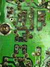
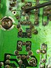
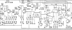
I dug out another from the bottom of the pile and I could not get it right until I removed this mod. I have seen it before. And have 3 radios in my parts radios with this same mod. Funny the mod mind not be too good. All 3 radios in the parts pile are pretty toasted. So here is a picture of the mod. Model, unmoved and screwdriver pointing to another trace jumped in the mod. By the way this is something to do with the pre. predriver.Q134.
 

Attachments

  • 20220126_104224.jpg
    20220126_104224.jpg
    1.9 MB · Views: 25
  • 20220126_104131.jpg
    20220126_104131.jpg
    1.8 MB · Views: 25
  • 20220126_104126.jpg
    20220126_104126.jpg
    1.7 MB · Views: 25
Last edited:

Not too good. The radio never worked right until I removed it. Showed modulation on FM. Showed most of the time a slight carrier on LSB. And would not tune right. With that mod removed the radio is working perfect although the same output power.
 
I have radios with that mod and never really knew what it was all about. And the radios usually worked hood with that mod. But this particular radio I have would not transmit correctly or transmit tune properly until I removed the mod. They also had a extra disc cap on the bottom of L111 which I removed also to get things working correctly. The signal is cleaner now also. I see no other mods on this radio.
 
If this could help @Low_Boy -there were other models in the era you mention that did pretty much the same thing.

Only the values were changed - but their support design did not deviate much from the OEM of the HR2510.

The Low-Level modulation scheme worked in specific ways to reduce the problems of modulation and excessive drive.
1643327157161.png
President Jackson
when compared to
1643327490077.png
HR2510
There were reasons why they did up the circuit using Common Emitter versus High-Side Collector coupling for the next stage - better control of the Dynamics - being impedance.

A wildly swinging radio puts the finals in jeopardy, let alone even the amps inputs can get damaged by the higher impulses present in collector connected outputs versus the Emitter coupled designs using a resistor as the "Shock absorber" while collector coupling the input resistor on top of the wildly swinging load the collector base then Emitter connection provided - I hope you get the idea - they just wanted to keep the swing in check.
 
Last edited:
If this could help @Low_Boy -there were other models in the era you mention that did pretty much the same thing.

Only the values were changed - but their support design did not deviate much from the OEM of the HR2510.

The Low-Level modulation scheme worked in specific ways to reduce the problems of modulation and excessive drive.
View attachment 56881
President Jackson
when compared to
View attachment 56882
HR2510
There were reasons why they did up the circuit using Common Emitter versus High-Side Collector coupling for the next stage - better control of the Dynamics - being impedance.

A wildly swinging radio puts the finals in jeopardy, let alone even the amps inputs can get damaged by the higher impulses present in collector connected outputs versus the Emitter coupled designs using a resistor as the "Shock absorber" while collector coupling the input resistor on top of the wildly swinging load the collector base then Emitter connection provided - I hope you get the idea - they just wanted to keep the swing in check.
It was sure swinging when I got it working. Especially with a transistor removed making the limiter useless. LOLO. But it came off the bottom of the pile and is now working.
 
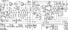
Common Collector (bypass cap on Collector, signal to next stage coming from Emitter) is a Current Amplifier, also called an Emitter Follower, where the Emitter Voltage "follows" the Base Voltage, minus the 0.7v Voltage drop across the Base/Emitter Diode region. This is what they designed the Jackson and HR series to use.
The mod @sp5it posted changes the Predriver from Common Collector to Common Emitter, by moving the bypass cap to the Emitter side, and feeding the next stage from the Collector, which makes it now a Voltage Amplifier. This increases the amount of RF each following stage receives from the previous.
I seem to remember having an adjusted 8w carrier on AM or FM before making this change, then after changing, it jumps up to at least 15w carrier, which needs to be readjusted back down to 8w. On SSB, this added at least an additional 5-10 watts to the PEP (clean on a scope pattern, ALC intact). The AM PEP (on scope) also increased, as there is now more "Headroom" for the RF to be able to use before flat topping (AMC intact too).
 
Last edited:
Common Collector (bypass cap on Collector, signal to next stage coming from Emitter) is a Current Amplifier, also called an Emitter Follower, where the Emitter Voltage "follows" the Base Voltage, minus the 0.7v Voltage drop across the Base/Emitter Diode region. This is what they designed the Jackson and HR series to use.
The mod @sp5it posted changes the Predriver from Common Collector to Common Emitter, by moving the bypass cap to the Emitter side, and feeding the next stage from the Collector, which makes it now a Voltage Amplifier. This increases the amount of RF each following stage receives from the previous.
I seem to remember having an adjusted 8w carrier on AM or FM before making this change, then after changing, it jumps up to at least 15w carrier, which needs to be readjusted back down to 8w. On SSB, this added at least an additional 5-10 watts to the PEP (clean on a scope pattern, ALC intact). The AM PEP (on scope) also increased, as there is now more "Headroom" for the RF to be able to use before flat topping (AMC intact too).
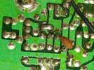
Thanks for the great explanation of how this mod works. I did find that the extra disc cap on the bottom of the board came off the top side ( I cant remember the number off hand ) All I can really say on this radio is it is working great now. And after removing that mod I have no more carrier on FM.
 
  • Like
Reactions: Handy Andy

dxChat
Help Users
  • No one is chatting at the moment.
  • dxBot:
    Tucker442 has left the room.
  • @ BJ radionut:
    LIVE 10:00 AM EST :cool:
  • @ Charles Edwards:
    I'm looking for factory settings 1 through 59 for a AT 5555 n2 or AT500 M2 I only wrote down half the values feel like a idiot I need help will be appreciated