

Uniden likes to use the chassis ground symbol for board ground and earth ground for chassis ground. Drives me nuts. The only way I keep it straight is the earth ground symbol looks like capacitor plates blocking DC.
Take this grant schematic for example. The antenna jack (which is on the chassis) shows an earth ground symbol and all the DC stuff uses the chassis ground symbol:
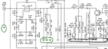
and I know it confuses them too, because when you get to the other side of the schematic, they swap those around. The 148 schematic is the same way.
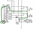
Where it appears they got them backwards here, I say this is the only place they got it half way right and that the rest of the schematic uses them wrong.
My opinion is that we should never use chassis ground symbols for DC negative when the actual chassis is intentionally isolated from it. If DC negative is not physically bonded to the chassis, the board grounds should show a single bar with -V under it. Signal ground has its own symbol too (that nobody uses, so I adopted it for DC ground).
Take this grant schematic for example. The antenna jack (which is on the chassis) shows an earth ground symbol and all the DC stuff uses the chassis ground symbol:
and I know it confuses them too, because when you get to the other side of the schematic, they swap those around. The 148 schematic is the same way.
Where it appears they got them backwards here, I say this is the only place they got it half way right and that the rest of the schematic uses them wrong.
My opinion is that we should never use chassis ground symbols for DC negative when the actual chassis is intentionally isolated from it. If DC negative is not physically bonded to the chassis, the board grounds should show a single bar with -V under it. Signal ground has its own symbol too (that nobody uses, so I adopted it for DC ground).