• You can now help support WorldwideDX when you shop on Amazon at no additional cost to you! Simply follow this Shop on Amazon link first and a portion of any purchase is sent to WorldwideDX to help with site costs.

Testing 1:1 balun

rixdafix

561 Missouri Mobile (WDX561)
Dec 19, 2022
111
291
73
East Central Missouri
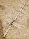
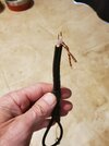
I'm going to start experimenting with GMRS Yagis and so now I'm building my first balun ever. The plan I'm using calls for a 1:1 coax balun using a 1/4 and 3/4 wave sections. Am I correct that I can connect a 50 ohm load across the leads and check impedance on my nanovna and adjust? I went ahead and tested it and it shows around 32 ohms and swr 1.6 at 465mhz (lower towards lower frequency). Shorten it a bit?

Thanks
20240226_162215.jpg
 

What was your final solution?
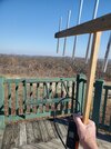
Well I cut all that extra shield off that I twisted together as i imagine that skews something, connected a 50 ohm load (that's used for calibrating my vna) across the feed and ended up snipping about 1/8" off the 1/4 wave section and about 3/8"off the 3/4 section. Got it real close to 50 ohms and swr around 1.25 at 465mhz. Took this rig to Taum Sauk mountain highest point in Missouri and made contacts through two repeaters 60 miles away on my Retevis HT. I'm happy.
20240302_090603.jpg
 
  • Like
Reactions: Shadetree Mechanic
A little more research leads me to think that wasn't the correct way to test the balun. The antenna works great though. I'm building a 12 element now and I'm just going to use the calculated measurements and see how it works. If anyone can give me insight on how to properly test a 1:1 UHF coax loop balun (if even possible with a nanovna) it would be appreciated.
 
Not sure why you want a 1:1 balun. The feed point of a split element driven on a yagi is not 50Ω. I also think that style balun uses common-mode current and messes with the antenna pattern. There are better options.

When you say you got real close to 50Ω with an SWR of 1.25, was that into the load resistor while adjusting the coax balun only, or with the balun connected to the antenna?

Coax for balun use is cut based on electrical length for the frequency. On the nano, you could connect the quarter wave section (set to CW, not sweep, at the center of desired band) and trim it until the trace stops a half revolution away on the other side of the smith chart. With the clipped end open (center not touching shield), the reading will be at the 0Ω side when clipped right for a quarter wavelength. With the 3/4 wave section connected, set it to center freq/3 and repeat. Then assemble the two together and test it into a load resistor. But again, that driven is not 50Ω, so why 1:1?

Why not go with a gamma match? It would let you keep the driven as one solid piece (more sturdy with staples) and provide a much better match. The usual starting point is with the gamma side of the driven element 2% shorter, the gamma rod half the diameter of the driven, 0.05λ long, spaced 0.007λ away, and with a series capacitance of about 7pF / meter of λ.

Ok, so these are baseline values commonly thrown around in HF discussions, but at 70cm, these values result in a really short gamma rod with a tiny spacing. This is where the gamma rod diameter can be made even smaller. What happens is the impedance ratio increases, which means you need more inductance to get up to the 50Ω constant conductance circle and the capacitance ends up being close to the same if the gamma side of the DE is not shortened. I've used 14awg copper wire to gamma match a 1/4" DE with a spacing of 1" at 1.25m, so with the nano, you can make a gamma rod out of just about anything that will hold up a chickadee cracking sunflowers.

With the nano (calibrated to the antenna's coax connector), start with no (or shorted) gamma capacitor so the gamma rod is connected directly to coax connector. Whatever size rod and spacing you choose, extend the rod/shorting bar to the point the nano reads 50Ω resistive, then whatever the reactance is, cancel it with series capacitance at the coax connector. Avoid dissimilar metals if possible.
 
  • Like
Reactions: rixdafix
Not sure why you want a 1:1 balun. The feed point of a split element driven on a yagi is not 50Ω. I also think that style balun uses common-mode current and messes with the antenna pattern. There are better options.

When you say you got real close to 50Ω with an SWR of 1.25, was that into the load resistor while adjusting the coax balun only, or with the balun connected to the antenna?

Coax for balun use is cut based on electrical length for the frequency. On the nano, you could connect the quarter wave section (set to CW, not sweep, at the center of desired band) and trim it until the trace stops a half revolution away on the other side of the smith chart. With the clipped end open (center not touching shield), the reading will be at the 0Ω side when clipped right for a quarter wavelength. With the 3/4 wave section connected, set it to center freq/3 and repeat. Then assemble the two together and test it into a load resistor. But again, that driven is not 50Ω, so why 1:1?

Why not go with a gamma match? It would let you keep the driven as one solid piece (more sturdy with staples) and provide a much better match. The usual starting point is with the gamma side of the driven element 2% shorter, the gamma rod half the diameter of the driven, 0.05λ long, spaced 0.007λ away, and with a series capacitance of about 7pF / meter of λ.

Ok, so these are baseline values commonly thrown around in HF discussions, but at 70cm, these values result in a really short gamma rod with a tiny spacing. This is where the gamma rod diameter can be made even smaller. What happens is the impedance ratio increases, which means you need more inductance to get up to the 50Ω constant conductance circle and the capacitance ends up being close to the same if the gamma side of the DE is not shortened. I've used 14awg copper wire to gamma match a 1/4" DE with a spacing of 1" at 1.25m, so with the nano, you can make a gamma rod out of just about anything that will hold up a chickadee cracking sunflowers.

With the nano (calibrated to the antenna's coax connector), start with no (or shorted) gamma capacitor so the gamma rod is connected directly to coax connector. Whatever size rod and spacing you choose, extend the rod/shorting bar to the point the nano reads 50Ω resistive, then whatever the reactance is, cancel it with series capacitance at the coax connector. Avoid dissimilar metals if possible.
Oh man thanks, great info and I appreciate you taking time to post that.

Impedance and SWR was initailly balun only into 50 ohm load with impedance around 45-46 ohms and SWR 1.25 and once assembled with antenna, pretty close to the same results.

I may be calling it a 1:1 balun mistakenly. Here is the site I used for calculations and it shows the loop construction and measurements but doesn't mention what ratio the balun is.
I used 465.000 MHz design frequency, 7 elements, .437" element diameter, isolated elements on 3/4" boom.

https://3g-aerial.biz/en/online-cal...ions/dl6wu-yagi-uda-antenna-online-calculator

I seem to recall the same design balun being referred to as 1:1 elsewhere so I went with calling it that. I was confused as well because I thought a dipole's characteristic impedance was around 73 ohms but I guess that's influenced by proximity of parasitic elements?

I had already planned on building my first gamma match on the next Yagi as it seems easier to adjust and with the info you provided I'll be much more confident doing so. At the time though, I only had material on hand to build the coax balun.

I might add, the antenna works great with potential for better I'm sure.

Thanks again for the help, Rick
 
Last edited:
  • Like
Reactions: brandon7861

dxChat
Help Users
  • No one is chatting at the moment.