• You can now help support WorldwideDX when you shop on Amazon at no additional cost to you! Simply follow this Shop on Amazon link first and a portion of any purchase is sent to WorldwideDX to help with site costs.

texas star 500 dx path of power in amp.

Regarding this 5 watt power resistor in the bias scheme. How long does it take to get hot?

And while you are testing this and keying it up has your balancing resistor in the output combiner (Near the relay) burned up yet? Doesn't take long.

And you said the resistors associated with the bias and your 10 ohm base resistors have been replaced?

Including the 1.6 or 1.8 ohm resistors by the input transformers?

Also, did you replace all 4 of these finals or just 2 of them?

And what prey tell did you use for replacements?

hfe matched HG transistors or "Toshiba" 2879s from ebay or maybe even legit shibas?

Good internal pics of the amp would help.

The very hot and cold power resistor in the bias scheme is screaming problem problem problem.
 
The 5-Watt resistor gets hot because it has power applied to it when the relay is keyed. Texas Star scrimped on the size of that resistor. 5 Watts is almost big enough, IMHO. A 10-Watt resistor would not run as hot. Or be as cheap. The one in the rear stays cold because no power is reaching it.

The fuseholder for the back pair of transistors has a wire that leads down to the rear pc board. Take the meter probe and see that this wire has power, and then follow the foil trace where it's soldered and see how far down the probe still shows power present.

Really sounds like a damaged foil trace on the rear pc board.

73
Will do. Thanks.
 
Please clarify for me.
You are saying no power to rear board.
Are you saying no voltage power to rear board ?
OR,
Are you saying no RF power to rear board ?

A couple of good photos would be helpful.
 
Please clarify for me.
You are saying no power to rear board.
Are you saying no voltage power to rear board ?
OR,
Are you saying no RF power to rear board ?

A couple of good photos would be helpful.
No voltage power. Not sure what the difference is. If you have no power, you have no voltage or RF power. Correct?
 
RF could be getting there to the board, but nothing would be happening if there is not any voltage getting to the transistors.
If I had that amplifier on my bench, first thing I would check for is DC voltage on the outboard end of the output transformer. If voltage is indicated, it should also be on the collectors of the power transistors.
Voltage or not, check the bias resistance on the input transformer end.
Hi Ranch55. I am not well schooled in electronics. If you could show me on a diagram where to check the DC voltage on the outboard end of the transformer that would help. Also can I check the power transistors for power on the collectors without removing the transistors? And where to check the bias resistance on the transformer input end? A diagram showing where to check for these things would be very helpful.

Thanks
 
RF could be getting there to the board, but nothing would be happening if there is not any voltage getting to the transistors.
If I had that amplifier on my bench, first thing I would check for is DC voltage on the outboard end of the output transformer. If voltage is indicated, it should also be on the collectors of the power transistors.
Voltage or not, check the bias resistance on the input transformer end.

Hi Ranch55. I am not well schooled in electronics. If you could show me on a diagram where to check the DC voltage on the outboard end of the transformer that would help. Also can I check the power transistors for power on the collectors without removing the transistors? And where to check the bias resistance on the transformer input end? A diagram showing where to check for these things would be very helpful.

Thanks
This might help with what Ranch55 is saying.
I highlighted the output transformer, the bias resistors, and the collectors of the transistors for you.
 

Attachments

  • DX500-400-667 test points.jpg
    DX500-400-667 test points.jpg
    428.7 KB · Views: 120
Power supply voltage to both ends of the output transformers, and to the collectors of both power transistors.
If voltage is present, then your initial statement of no power to rear board is inaccurate.
Hence, my question of "voltage power or RF power".
 
Power supply voltage to both ends of the output transformers, and to the collectors of both power transistors.
If voltage is present, then your initial statement of no power to rear board is inaccurate.
Hence, my question of "voltage power or RF power".
Thanks Ranch 55. I will test for voltage at those locations and let you know what I find. It might take a few days with my medical tests coming up.
 
Regarding this 5 watt power resistor in the bias scheme. How long does it take to get hot?

And while you are testing this and keying it up has your balancing resistor in the output combiner (Near the relay) burned up yet? Doesn't take long.

And you said the resistors associated with the bias and your 10 ohm base resistors have been replaced?

Including the 1.6 or 1.8 ohm resistors by the input transformers?

Also, did you replace all 4 of these finals or just 2 of them?

And what prey tell did you use for replacements?

hfe matched HG transistors or "Toshiba" 2879s from ebay or maybe even legit shibas?

Good internal pics of the amp would help.

The very hot and cold power resistor in the bias scheme is screaming problem problem problem.
Sorry I did not see your message right away. My bad. The 5 watt wire wound resister gets too hot to touch in a few seconds. All resistors wqere replaced with ones of equal values. All 4 final power transistors were replaced with toshiba 2879s not fakes that you get from ebay. I do not have ability to take and send photos. Sorry,I am old do not have a modern smart phone to do that. Any advice is appreciated!

Thank you kc8mob
 
Here is a good writeup guide. Not by me, but I'm in agreement.

Hi Dan here in Conway S.C. AKA TURBO.
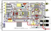
Here is a cheat sheet i made up...Use this first.

No receive:

when the power is on, does the light behind the meter turn on?

if the meter light turns on without being keyed up, then the keying transistor is shorted. Remove the 2n2907a which is located behind the relay.
now the lamp should not turn on.


if the meter lamp does not turn on and there is not receive, I expect that the receive transistor is not working. Replace the transistor behind the receive switch.

Use a 2907a


No transmit output:


let's back up and start from scratch.

Turn the amp off. Key the radio. The radio should pass radio power straight through it and should have a low SWR. If the straight through condition is not A-OK, we need to fix that before we do anything else.

Turn on amp and key up radio. Does the relay click? Does the meter lamp light up while radio is keyed up?

If the relay doesn't click and meter lamp turn on, replace the keying transistor with a new 2n2907a.

Now if the relay does click and if the meter lamp does turn on while keyed, is there any power output from the amp.

No output can mean blown power transistors (commonly called pills).

Checking the Pills:

Now we need to determine if the transistors are ok or if they are blown.

With the power turned on read the voltage on the top lead (collector) of the transistors. We want full B+ here, 13.8 volts d.c.

More than that and you blew the transistors. Less than that and you have an open circuit. This is connected directly to the fuse connector.

Now check the voltage at the bottom lead (base) of the transistors. This should read 00 volts d.c.

If you read any voltage here now, you have leaky transistors. They will need to be replaced. Read the cautions in next section.

You can check the transistors without removing them, but you do need to get them out of the circuit. This is called floating the transistors. Carefully lift the top tabs (collectors) so they do not touch the traces. Now carefully remove the bottom tabs (bases) so that they do not touch the traces. The transistor pair is now out of the circuit. Now you need to check the resistances.

Connect the black lead of your ohmmeter to the top tab and the red lead to the bottom lead. This is your collector base junction and it should read about 600 ohms. Now connect the black lead to the ground trace (emmiter) and the red lead to the bottom tab (base). This should also read about 600 ohms. It will be common to find open or shorted junctions. This indicates a blown transistor. If these resistances are as I say, the transistors are good.

Before changing transistors please read the cautions in the next section.

Burnt bias resisistors always indicates blown transistors.

When changing the two 10 ohm resistors you will be well advised to also change the 1.6 or 1.8 ohm resistor also.


Changing the Pills:


When replacing transistors on a Texas Star amplifier, it is imperative to ALWAYS check the bias circuit of the transistor pair.

There will always be two 10ohm resistors from the bases AND a 1.6 (or 1.8) ohm resistor from the bead wires to ground.

Look for about 1.3 ohms to ground from the input transformer (or the transistor bases).

Note: If you read 5 ohms that’s the 2 tens, and the 1.6 is open.

(exception is 667 and 667v- front board has 2 - 10s and a 2.7 ohm and driver has a 6.2 ohm to

ground for equivalent resistance)

Now, if you are sure that the effective resistance is correct, manually key-up the amp and check the voltage at the input transformer (transistor bases).

It must be 0.6 volts d.c. **** *** OR DO NOT key rf into the amp.

If this voltage is 0.0 volts there is a short in the bias circuit

If this voltage is > 0.6 volts then there is a bias resistance problem or a leaky transistor


Manual key-up procedure:

Behind the relay there is a 470 ohm resistor. The side closest to the relay is the emitter of the

keying transistor. Short this point to ground with a screwdriver and the relay will manually key up


Burnt toroids:


Amplifier boards each have a pair of transistors. Two boards can be combined for a more powerful amplifier. The input signal will go to a separator toroid and the outputs will combine at another toroid.

Simple concept. But both amp boards must be exactly the same as each other. If one has less power or fails entirely, the combiner toroid will burn. Therefore, a burnt toroid indicates that the transistors on one board or both are blown and require replacement.


Precautions:

Make sure that you are using a properly installed ground plane antenna system. Run ground straps from your vehicle frame to the antenna bracket. Even if this is a mirror mount. Do not ever use a magnetic mount antenna system.


Make sure that the coax connector grips the antenna center conductor. These connections commonly fail and you will have an effective open circuit.


Make sure that supplied voltage is at 13.8 volts d.c. and not more or less. Insufficient power connections will cause low power output.


Make sure that the radio output wattage is not more than the rated input for the amplifier.

Troubleshooting:

First we need to really determine exactly what is wrong.

I will describe some common conditions and go from there.

No receive:

when the power is on, does the light behind the meter turn on?


if the meter light turns on without being keyed up, then the keying transistor is shorted. Remove the 2n2907a which is located behind the relay.

now the lamp should not turn on.


if the meter lamp does not turn on and there is not receive, I expect that the receive transistor is not working. Replace the transistor behind the receive switch.

Use a 2907a

Hope this helps.:pop:
 

dxChat
Help Users
  • No one is chatting at the moment.
  • dxBot:
    Tucker442 has left the room.
  • @ BJ radionut:
    LIVE 10:00 AM EST :cool:
  • @ Charles Edwards:
    I'm looking for factory settings 1 through 59 for a AT 5555 n2 or AT500 M2 I only wrote down half the values feel like a idiot I need help will be appreciated