I know you can change R114 for a 10k ohm for a better audio response in a Cobra 2000 but what about a Uniden Madison? I looked inside but its not the same board layout as my Cobra 2000 so i was wondering if this kind of mod can be done to this radio and where is the location for it. Thanks!

You are using an out of date browser. It may not display this or other websites correctly.
You should upgrade or use an alternative browser.
You should upgrade or use an alternative browser.
-
You can now help support WorldwideDX when you shop on Amazon at no additional cost to you! Simply follow this Shop on Amazon link first and a portion of any purchase is sent to WorldwideDX to help with site costs.
The R114 Mod.
- Thread starter King Mudduck
- Start date
hey KM,
i found R114 in the uniden madison.
first find L2, which is in the front right portion of the PC board.
directly to its right, you will find C99, an electrolytic capacitor.
directly to the right of C99, you will find R114.
also, C46 is right behind R114.
on a side note, while looking for this, i noticed that the uniden madison has no internal adjustment for AMC.
in the mobile versions, its VR7.
in the 2000GTL, its VR12.
in the madison, VR7 is for the modulation meter, and VR12 is for the AWI (antenna warning indicator).
anyone know which internal fixed resistor should be replaced with a VR to give the radio an internal AMC adjustment?
any other thoughts on this?
later,
LC

I just wonder if changing R114 in this radio will have the same affect as it did on my 2000? Would hate to do this and the radio go poof!
radio will not go poof.
R114 and C46 do the same thing in both radios.
i have a madison that i am restoring, and i will be doing this mod to it when i get it up and running.
good luck,
LC
R114 and C46 do the same thing in both radios.
i have a madison that i am restoring, and i will be doing this mod to it when i get it up and running.
good luck,
LC
I haven't worked in the CB field since 2000, but I used to put AMC pots on the boards of Madisons and Washingtons all the time when I worked on them. I can't remember what fixed resistor I swapped out to put the variable pot in it's place, but it is do-able. I also had the complete Sams Photofact library above my head at the time, so I had good reference material. I can't find a schematic on either MB8719 versions of the President McKinley or Madison radios on CBTricks or any other.
Well I did clip r104 just to see if that was indeed the mod limiter and it is. It's now flat topping on the scope. Just wondering if it's plug n play with the variable pot. Thanks
what value is R104? I think I used a 5k pot, but it was LONG ago, in a state far away from me now.
And, are there holes on the board there by the transformer for a pot, just to the inside near where the final and driver jumpers are to set the bias? I can't remember.
And, are there holes on the board there by the transformer for a pot, just to the inside near where the final and driver jumpers are to set the bias? I can't remember.
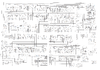
Take what you need , I've used bits and pieces for my Madison projects, tried to piece together a few schematics on one to try make it easier for myself. Hope this helps. Also the Simpson Bengal MKIII uses the same board
Attachments
I looked over the schematics for the Washington PC385 board, which is the same as your McKinley PC385, R104 (10k) was not the correct part to cut/change, but R105 (1.5k Brn/Grn/Red) was. Remove R105, and put a 1N4148 diode with the non-bar end in the hole that R105 was connected to the base of TR33. and the bar end (Cathode) would go to a 500 Ohm variable potentiometer to ground.
This makes it exactly like a Cobra 2000GTL, 148, Grant XL, etc... in that circuit.
The collector of TR33 goes to C90, a 10uF/16v electrolytic capacitor, which has one side going to +8v, other side also goes through R131 (15k) then to the base of TR31, a PNP transistor. This Cap C90, is the "sample and hold" part where the AMC and ALC are tied together. Put a 22k across this cap on the solder side of the board, this will cause it to release faster, and you now have to readjust your newly added AMC pot and the ALC for SSB as well.
If you have an oscilloscope, turn the ALC all the way up, then key up and while saying "EH" like the middle of hello into the microphone, back the ALC until the tops are curvy, but not too much to where it clamps the audio too much. It will look like a sideways fat Christmas tree on the scope pattern, rather than a triangular christmas tree. Do the same with the AMC in AM mode, curves on the tops, but not flat topping in the middles, try to minimize the pinch points, where the signal pinches to zero in between each curve.
This makes both of the ALC and AMC act like a Sylabic Speech Processor, opens up the audio, but still not allow it to overmodulate.
The 3 components to change or add are
D-ADD (1N4148)
VR-ADD (500 Ohm linear taper pot)
R-ADD (22k to put in parallel with C90)


In the Madison, it would be R130 (1.5k) to change to a diode and 500 Ohm pot, and add on 22k to C109.

This makes it exactly like a Cobra 2000GTL, 148, Grant XL, etc... in that circuit.
The collector of TR33 goes to C90, a 10uF/16v electrolytic capacitor, which has one side going to +8v, other side also goes through R131 (15k) then to the base of TR31, a PNP transistor. This Cap C90, is the "sample and hold" part where the AMC and ALC are tied together. Put a 22k across this cap on the solder side of the board, this will cause it to release faster, and you now have to readjust your newly added AMC pot and the ALC for SSB as well.
If you have an oscilloscope, turn the ALC all the way up, then key up and while saying "EH" like the middle of hello into the microphone, back the ALC until the tops are curvy, but not too much to where it clamps the audio too much. It will look like a sideways fat Christmas tree on the scope pattern, rather than a triangular christmas tree. Do the same with the AMC in AM mode, curves on the tops, but not flat topping in the middles, try to minimize the pinch points, where the signal pinches to zero in between each curve.
This makes both of the ALC and AMC act like a Sylabic Speech Processor, opens up the audio, but still not allow it to overmodulate.
The 3 components to change or add are
D-ADD (1N4148)
VR-ADD (500 Ohm linear taper pot)
R-ADD (22k to put in parallel with C90)
In the Madison, it would be R130 (1.5k) to change to a diode and 500 Ohm pot, and add on 22k to C109.