Hi all,
First post here. Thanks to an older thread on here I found the schematic for a Turner Super Sidekick, as I was recently given one (among other things) for Christmas...kind of like a grab bag of semi-working stuff (which I may need to make a thread about to get some answers on those who may understand more than I do).
I'm fairly new to radios of any sort, and have kicked around modifying tube guitar amps and effects pedals for about a decade.
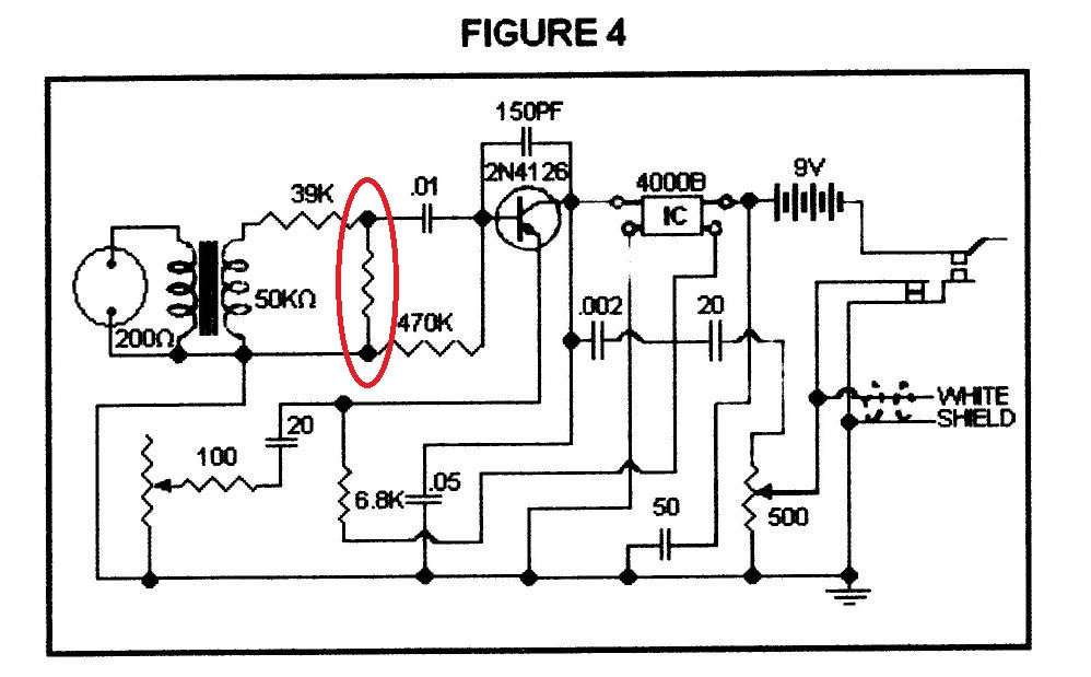
Anyway, Does anyone have a picture available of the component side of a Super Sidekick board? There is a missing resistor, and the schematic shows it, but has no value beside it. It should be connected to both legs of the primary side of the transformer. I've attached the .pdf containing the schematic.
Any help would be much appreciated, and thanks ahead of time.
First post here. Thanks to an older thread on here I found the schematic for a Turner Super Sidekick, as I was recently given one (among other things) for Christmas...kind of like a grab bag of semi-working stuff (which I may need to make a thread about to get some answers on those who may understand more than I do).
I'm fairly new to radios of any sort, and have kicked around modifying tube guitar amps and effects pedals for about a decade.
Anyway, Does anyone have a picture available of the component side of a Super Sidekick board? There is a missing resistor, and the schematic shows it, but has no value beside it. It should be connected to both legs of the primary side of the transformer. I've attached the .pdf containing the schematic.
Any help would be much appreciated, and thanks ahead of time.