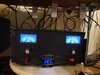
Finally accumulated the necessary parts to upgrade the amplifier board in my DX98VHP. First thing was to check the power output without the amplifier section on to insure I wasn’t going to overdrive the new board. Looks good only about 0-2.5 watts dead key with mic gain off. PEP is 44 watts.
Took my time yesterday (Sunday) while the wife was shopping and spent about four hours doing the upgrade. First thing was to take extensive pictures to insure everything went back correctly. This is the second upgrade I have performed on these radios.
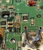
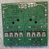
Proceeded to remove old amp board as pictured before…8 mosfet’s. I was going to replace the cooling fans with some 4500 rpm 40mm fans abut wanted to verify how the factory fans performed. Much to my surprise the factory fans displaced more air than the Noctura fans I had purchased, so they stayed installed.
Next was to select a medium sized chisel soldering iron tip. Using my Weller WE1010NA with temperature set to 800 degrees, I proceeded to remove the B+ and B- power connections and the antenna leads coming from the pigtail. During this process I discovered that the antenna lead coming from the Radio’s main board to the amp board literally fell out when I touched it…Not Good.
Cleaned up the thermal paste from the Amp housing and grab my SYY-157 Thermal Paste and began to apply. Unfortunately both tubes were dried out and useless after only 5 months. Grabbed the backup Arctic Silver 5. Using a credit card size piece of plastic I evenly spread the thermal paste. Installed the new amp board next. No I did not pre-solder the Toshiba’s on the amp board, as I wanted to insure there was a total surface area contact between the Toshiba’s and the heat sink and that the screw holes all lined up properly.
With amp board installed I very thinly coated each 2879 with thermal paste a habit from my computer building days. Cinched them down and proceeded to solder them using the Weller WE101NA still set to 800 degrees with the medium size chisel tip. Using Kester 63/37 alloy and .061 size solder we went to work. That was easy peezy. Next the negative feedback boards. Of course one fit right in and the other one needed to have the ends trimmed with my razor knife. After multiple shaves/trims on both ends it fit right in. After soldering them in place it was time to inspect my work. At this point I took my multimeter set for continuity and checked everything out. Everything looked good…Bells CB could use a few pointers on soldering…LOL.
Now it was time to fix that antenna plug in jack. The male connector has two tabs which are suppose to slide in between two slots on the female board connector…Geeze we have a slot on top but none on the bottom…do I remove the bottom tab or do something else. I remembered from the first DX98VHP I ever did how impossible it was to pull that plug out without using small needle nose pliers. Well the route I choose was to solder it in place. Using the connector I plugged in the cable as tightly as possible and tack soldered the outside ground on the pin and connector. Try pulling that out would you. On another note I have RG316DS on hand. So far the smallest connector I’ve found is sma. Thought about replacing the cable from the radio to the amp board and making it a smidge longer so that one could work on it. Would prefer a mini connector like what’s already on the board…male/female ends. Can someone point me in the right direction? Waiting to call Barkett and Galaxy to secure the necessary parts. Necessary parts have been ordered from Barkett….YAY. Gregory the owner is Fantastic! So updating the antenna connection will wait until another day. I don’t think the amp board will need to be removed as I’m thinking I’ll just snip off one of the tabs/wings on the male end so it will fit the amp board connector.
Hooked all the connections back up and now it was time before assembly to apply power for the first smoke test. With radio connected to dummy, RF power low, mic gain off and Amp switch off I turned it on. No smoke…WHEW but no Audio either…what the hell. Close inspection revealed I missed the two pins when re-connecting the speaker…geez Brad are you BLIND? Reconnected the plug in and viola we have sound. Next step is to turn on the amp switch. Second smoke test passed. With mic gain off I keyed up. Third smoke test….passed. Fans are working properly the Toshiba’s are stone cold and amp draw is about 30amps.
Replaced the cover on the amp board and proceeded to make sure I wasn’t pinching any wires and put the case back together. With everything assembled and back in it’s place it was time for a radio check on 19. “Sounds good driver…what’s you running there?” Ah the audio of a Galaxy with Silver K Eagle is just WOW.
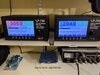
Power output with the 8 mosfets was 294 PEP.
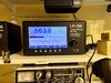
Power output with the four Toshiba’s 563 PEP.
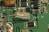
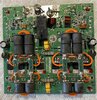
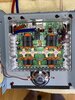
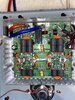
Ah the look, sound and smell of success! First picture below is showing the original output before upgrade. Next two pictures the original amp board removed (which I may sell). Next picture of new amp board with Toshiba’s prior to soldering. Next picture everything soldered up.
The DX98VHP is now a stand alone radio not connected to any amplifier.
That’s all folks.
Brad
KE0XS
South of Pittsburgh
Took my time yesterday (Sunday) while the wife was shopping and spent about four hours doing the upgrade. First thing was to take extensive pictures to insure everything went back correctly. This is the second upgrade I have performed on these radios.
Proceeded to remove old amp board as pictured before…8 mosfet’s. I was going to replace the cooling fans with some 4500 rpm 40mm fans abut wanted to verify how the factory fans performed. Much to my surprise the factory fans displaced more air than the Noctura fans I had purchased, so they stayed installed.
Next was to select a medium sized chisel soldering iron tip. Using my Weller WE1010NA with temperature set to 800 degrees, I proceeded to remove the B+ and B- power connections and the antenna leads coming from the pigtail. During this process I discovered that the antenna lead coming from the Radio’s main board to the amp board literally fell out when I touched it…Not Good.
Cleaned up the thermal paste from the Amp housing and grab my SYY-157 Thermal Paste and began to apply. Unfortunately both tubes were dried out and useless after only 5 months. Grabbed the backup Arctic Silver 5. Using a credit card size piece of plastic I evenly spread the thermal paste. Installed the new amp board next. No I did not pre-solder the Toshiba’s on the amp board, as I wanted to insure there was a total surface area contact between the Toshiba’s and the heat sink and that the screw holes all lined up properly.
With amp board installed I very thinly coated each 2879 with thermal paste a habit from my computer building days. Cinched them down and proceeded to solder them using the Weller WE101NA still set to 800 degrees with the medium size chisel tip. Using Kester 63/37 alloy and .061 size solder we went to work. That was easy peezy. Next the negative feedback boards. Of course one fit right in and the other one needed to have the ends trimmed with my razor knife. After multiple shaves/trims on both ends it fit right in. After soldering them in place it was time to inspect my work. At this point I took my multimeter set for continuity and checked everything out. Everything looked good…Bells CB could use a few pointers on soldering…LOL.
Now it was time to fix that antenna plug in jack. The male connector has two tabs which are suppose to slide in between two slots on the female board connector…Geeze we have a slot on top but none on the bottom…do I remove the bottom tab or do something else. I remembered from the first DX98VHP I ever did how impossible it was to pull that plug out without using small needle nose pliers. Well the route I choose was to solder it in place. Using the connector I plugged in the cable as tightly as possible and tack soldered the outside ground on the pin and connector. Try pulling that out would you. On another note I have RG316DS on hand. So far the smallest connector I’ve found is sma. Thought about replacing the cable from the radio to the amp board and making it a smidge longer so that one could work on it. Would prefer a mini connector like what’s already on the board…male/female ends. Can someone point me in the right direction? Waiting to call Barkett and Galaxy to secure the necessary parts. Necessary parts have been ordered from Barkett….YAY. Gregory the owner is Fantastic! So updating the antenna connection will wait until another day. I don’t think the amp board will need to be removed as I’m thinking I’ll just snip off one of the tabs/wings on the male end so it will fit the amp board connector.
Hooked all the connections back up and now it was time before assembly to apply power for the first smoke test. With radio connected to dummy, RF power low, mic gain off and Amp switch off I turned it on. No smoke…WHEW but no Audio either…what the hell. Close inspection revealed I missed the two pins when re-connecting the speaker…geez Brad are you BLIND? Reconnected the plug in and viola we have sound. Next step is to turn on the amp switch. Second smoke test passed. With mic gain off I keyed up. Third smoke test….passed. Fans are working properly the Toshiba’s are stone cold and amp draw is about 30amps.
Replaced the cover on the amp board and proceeded to make sure I wasn’t pinching any wires and put the case back together. With everything assembled and back in it’s place it was time for a radio check on 19. “Sounds good driver…what’s you running there?” Ah the audio of a Galaxy with Silver K Eagle is just WOW.
Power output with the 8 mosfets was 294 PEP.
Power output with the four Toshiba’s 563 PEP.
Ah the look, sound and smell of success! First picture below is showing the original output before upgrade. Next two pictures the original amp board removed (which I may sell). Next picture of new amp board with Toshiba’s prior to soldering. Next picture everything soldered up.
The DX98VHP is now a stand alone radio not connected to any amplifier.
That’s all folks.
Brad
KE0XS
South of Pittsburgh
Attachments
-
 7EF9206A-1740-45A8-99BB-F7BBC9D85195.jpeg1 MB · Views: 60
 -
 E21A56CD-981E-4FCA-A54E-C81C0B02238B.jpeg1.8 MB · Views: 54
 -
 8DDF3F75-BDE8-4A18-8183-50C0FD5F9E70.jpeg1.4 MB · Views: 65
 -
 DFE7A2BF-8B2C-4CE8-BD24-C421BE0C4493.jpeg1.9 MB · Views: 72
 -
 945B4E59-0279-4CC0-B49D-0EDD96FAA82E.jpeg1.8 MB · Views: 74
 -
 2BDDA4F2-0F6A-454D-BFE2-0A71395FD223.jpeg2 MB · Views: 70
Last edited: